ISSN ONLINE(2320-9801) PRINT (2320-9798)
ISSN ONLINE(2320-9801) PRINT (2320-9798)
Iswarya Gopal, Rajasekar .T
|
| Related article at Pubmed, Scholar Google |
Visit for more related articles at International Journal of Innovative Research in Computer and Communication Engineering
Transient multiple cell upsets (MCUs) are becoming major issues in the reliability of memories exposed to radiation environment. To prevent MCUs from causing data corruption, more complex error correction codes (ECCs) are widely used. The soft error rate in memory cells Multiple Cell Upset (MCU) are rapidly increasing. MCU have become a serious reliability issue in the memory. A novel Decimal Matrix Code (DMC) based on divide- symbol is proposed to enhance memory reliability with lower delay overhead. The proposed DMC utilizes decimal algorithm to obtain the maximum error detection capability. The Encoder-Reuse Technique (ERT) is proposed to minimize the area overhead of extra circuits without disturbing the whole encoding and decoding processes. ERT uses DMC encoder itself to be a part of the decoder. The increasing density of NAND flash memory leads to a dramatic increase in the bit error rate of flash, which greatly reduces the ability of error correcting codes (ECC) to handle multibiterrors.Meta-Cure exploits built-in ECC and replication in order to protect pages containing critical data, such as file system metadata. Redundant pairs are formed at run time and distributed to different physical pages to protect against failure.
KEYWORDS |
| Decimal algorithm, error correction codes (ECCs), memory, multiple cells upsets (MCUs), meta-cure. |
I. INTRODUCTION |
| Single bit upset is a major concern about memory reliability, transient multiple cell upsets (MCUs) are becoming major issues in the reliability of memories exposed to radiation environment. To prevent MCUs from causing data corruption, more complex error correction codes (ECCs) are widely used to protect memory, but the main problem is that they would require higher delay overhead. Recently, matrix codes (MCs) based on hamming codes have been proposed for memory protection. The main issue is that they are double error correction codes and the error correction capabilities are not improved in all case. |
| 1.1 Error Correction Codes: An error-correcting code (ECC) or forward error correction (FEC) code is a system of adding redundant data, or parity data, to a message, such that it can be recovered by a receiver even when a number of errors (up to the capability of the code being used) were introduced, either during the process of transmission, or on storage. Since the receiver does not have to ask the sender for retransmission of the data, a back-channel is not required in forward error correction, and it is therefore suitable for simplex communication such as broadcasting. Errorcorrecting codes are frequently used in lower-layer communication, as well as for reliable storage in media such as CDs, DVDs, hard disks, and RAM. |
| 1.2 Memory: The term "memory" meaning primary memory is often associated with addressable semi-conductor memory, i.e. integrated circuits consisting of silicon based transistors, used for example as primary memory but also other purposes in computers and other digital electronic devices. There are two main types of semiconductor memory volatile and non-volatile memory. |
II. RELATED WORK |
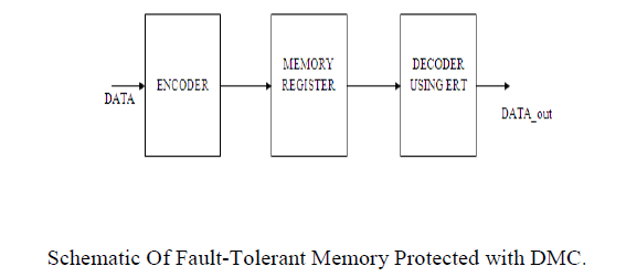
| Schematic For Fault-Tolerant Memory:The proposed schematic of fault-tolerant memory is depicted in Fig. 1. First, during the encoding (write) process, information bits D are fed to the DMC encoder, and then the horizontal redundant bits H and vertical redundant bits V are obtained from the DMC encoder. When the encoding process is completed, the obtained DMC code word is stored in the memory. If MCUs occur in the memory, these errors can be corrected in the decoding (read) process. Due to the advantage of decimal algorithm, the proposed DMC has higher fault-tolerant capability with lower performance overheads. In the fault-tolerant memory, the ERT technique is proposed to reduce the area overhead of extra circuits. It uses addition of integer values to detect and correct soft errors. |
 |
| Proposed DMC Encoder: In the proposed DMC, first, the divide-symbol and arrange-matrix ideas are performed, i.e., the N-bit word is divided into k symbols of m bits (N = k × m), and these symbols are arranged in a k1 × k2 2-D matrix (k = k1 × k2, where the values of k1 and k2 represent the numbers of rows and columns in the logical matrix respectively). Second, the horizontal redundant bits H are produced by performing decimal integer addition of selected symbols per row. Here, each symbol is regarded as a decimal integer. Third, the vertical redundant bits V are obtained by binaryoperation among the bits per column. It should be noted that both divide-symbol and arrange-matrix are implemented in logical instead of in physical. Therefore, the proposed DMC does not require changing the physical structure of the memory. |
 |
| To explain the proposed DMC scheme, take a 32-bit word as an example, as shown in Fig. 2. The cells from D0 to D31 are information bits. This 32-bit word has been divided into eight symbols of 4-bit. k1=2 and k2=4 have been chosen simultaneously. H0–H19 are horizontal check bits; V0 through V15 are vertical check bits. However, it should be mentioned that the maximum correction capability (i.e., the maximum size of MCUs can be corrected) and the number of redundant bits are different when the different values for k and m are chosen. Therefore, k and m should be carefully adjusted to maximize the correction capability and minimize the number of redundant bits. For example, in this case, when k = 2×2 and m = 8, only 1-bit error can be corrected and the number of redundant bits is 40. When k = 4 × 4 and m = 2, 3-bit errors can be corrected and the number of redundant bits is reduced to 32. However, when k = 2 × 4 and m = 4, the maximum correction capability is up to 5 bits and the number of redundant bits is 34. In order to enhance the reliability of memory, the error correction capability is first considered, so k = 2 × 4 and m = 4 are utilized to construct DMC |
| Horizontal Redundant Bit :The horizontal redundant bits H can be obtained by xor the data bits as follows: |
| H4H3H2H1H0=D3D2D1D0⊕D11D10D9D8(1) |
| H9H8H7H6H5=D7D6D5D4⊕D15D14D13D12 (2) |
| and similarly for the horizontal redundant bits H14H13H12H10 and H19H18H17H16H15, where “+” represents decimal integer addition. |
| Vertical Redundant Bit: The vertical redundant bits V, can be obtained by decimal and binary operation |
| V0=D0⊕D16 (3) |
| V1=D1⊕D17 (4) |
| and similarly for the rest vertical redundant bits. The encoding can be performed by decimal and binary addition operations from (1) to (4). The encoder that computes the redundant bits using multibit adders and XOR gates is shown |
| Proposed DMC Decoder: To obtain a word being corrected, the decoding process is required. For example, first, the received redundant bits H4H3H2H1H0` and V0` − V3 ` are generated by the received information bits D`. Second, the horizontal syndrome bits ΔH4H3H2H1H0 and the vertical syndrome bits S3 − S0 can be calculated as follows |
| ΔH4H3H2H1H0 = H4H3H2H1H0’- H4H3H2H1H0 (5) |
| S0=V0’⊕V0 (6) |
| and similarly for the rest vertical syndrome bits, where “−” represents decimal integer subtraction. When ΔH4H3H2H1H0 and S3 − S0 are equal to zero, the stored code word has original information bits in symbol 0 where no errors occur. When ΔH4H3H2H1H0 and S3 − S0 are nonzero, the induced errors (the number of errors is 4 in this case) are detected and located in symbol 0, and then these errors can be corrected by |
| D0correct = D0⊕S0 (7) |
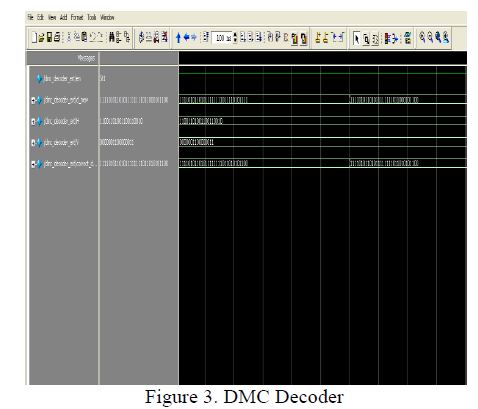
| The proposed DMC decoder is depicted in Fig. 3.4, which is made up of the following sub modules, and each executes a specific task in the decoding process: syndrome calculator, error locator, and error corrector. It can be observed from this figure that the redundant bits must be recomputed from the received information bits D` and compared to the original set of redundant bits in order to obtain the syndrome bits ΔH and S. Then error locator uses ΔH and S to detect and locate which bits some errors occur in. Finally, in the error corrector, these errors can be corrected by inverting the values of error bits. |
III. PROPOSED ALGORITHM |
| A. Encoding / Decoding Algorithm |
| The proposed code is systematic. During encoding, the data bits can be directly copied and the check bits are generated using an XOR network corresponding to the Matrix. |
| The decoding algorithm is as follows: |
| 1) Generate the syndrome using an XOR network corresponding to the H-matrix. |
| 2) If the syndrome is the all zero vector, then no error is detected, otherwise one or more errors occurred. |
| 3) If the syndrome matches any of the H-matrix columns, then a single error is detected and the error position is the corresponding column position. The corresponding bit should be flipped to correct the error. |
| 4) Else if the syndrome matches any of the n-1 adjacent double error syndromes, then a double adjacent error is detected and the corresponding bit positions are generated using the error correction logic. |
| 5) Else an uncorrectable error (UE) (i.e., a double non adjacent error or more than two errors) has occurred. |
| The only additional overhead with respect to a conventional SEC-DED code comes from step 4 of the decoding step. Figure 5 shows the basic error detection and correction block diagram. If a non-zero syndrome is encountered, then the OR gate flags an error indication. If the syndrome matches any of the single error syndromes then the syndrome decoder generates a 1 in the erroneous bit position. Otherwise, if the syndrome matches any of the adjacent double error syndromes, then the decoder generates 1’s at the erroneous adjacent bit positions. Otherwise the output of the syndrome decoder is the all zero output. The syndrome decoder consists of 3-input OR gates whose inputs are driven by outputs of r-input AND gates. The i-th output of the decoder is 1 if and only if a single error occurred at the i-th bit or a double adjacent error occurred at <i,i+1> bits or <i-1,i> bits. The outputs of the decoder are used to generate the corrected word, by using n 2-input XOR gates. If the syndrome is non-zero and does not match any of the single or double adjacent error syndromes, then the UE signal is flagged. |
IV. SIMULATION RESULTS |
| The proposed DMC has been implemented in VERILOG, simulated with ModelSim and tested for functionality by given various inputs. The encoder and decoder have been synthesized by the XILINX 0.18μm technology. The area, power, and critical path delay of extra circuits have been obtained output. |
 |
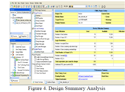
| The figure 4 shows that the total equivalent gate count which is 893 using Xilinx software this gate count may varies with corresponding kit. |
 |
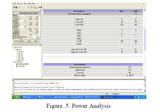
| The figure.5 gives the power analysis of a given DMC decoder that the total power obtained is 752.74 using the Xilinx software. |
 |
V. CONCLUSION AND FUTURE WORK |
| The proposed protection code utilized decimal algorithm to detect errors, so that more errors were detected and corrected. The obtained results showed that the proposed scheme has a superior protection level against large MCUs in memory and redundant are reduced. Therefore, future work will be conducted for the proposed technique and its implementation. |
References |
|