ISSN ONLINE(2278-8875) PRINT (2320-3765)
ISSN ONLINE(2278-8875) PRINT (2320-3765)
A.Priyanka1, Dr. T. Gowri Manohar2, N. Damodar3
|
| Related article at Pubmed, Scholar Google |
Visit for more related articles at International Journal of Advanced Research in Electrical, Electronics and Instrumentation Engineering
To reduce AT & C losses in power distribution sector so many measures have been taken and so many methods have been adopted in power distribution sector. Apart from this, Indian power sector is concentrating on energy audit at different levels i.e., at consumer end, DTR end, 11kv feeder end and substation level. At this juncture power utilities have been taken the step to adopt AMR system to capture energy meter data of the 11 Kv feeders from remote end to measure the energy consumption and compare the sold energy with measured energy and to derive AT & C loss of that particular feeder and finally achieved significant loss reduction by AMR system. In this paper a new AMR method based on GPRS technique is implemented and data acquisitioned into MDAS Application.
Keywords |
| AMR, DLMS meters, GSM/ GPRS SIMs, MDAS. |
INTRODUCTION |
| Nowadays electricity places a key role in the human life. Without electricity, life will be very difficult. Various scientific inventions have made this world worth living. They made our human lives more luxurious and comfortable. The invention of electricity is one of the greatest achievements of man. Apart from its social benefits, electricity is also a driving factor in the economy. Today's digital world totally driven power sector only. Its usage ranges from communication and transportation to production. So, proper utilization of electricity is of great important to us. In order to meet the power demand and for the future developments of power system network , it is necessary to measure power consumption to evaluate AT&C losses. In today's world everything has become automated to reduce the human effort, hence in this paper automatic meter reading (AMR) is used for capturing the electrical energy meter data from the meters located at remote end. AMR system is the modern system used to read meter data from server end and to facilitate to generate different kinds of reports including billing .In many countries in this world are using automatic meters since it has a lot of advantages than legacy methods. It has advantages in safety , real time measurement and time saving as well as it has a better user interface and digital data analysis . Data is send over existing carrier that reduces the complexity and cost of system. |
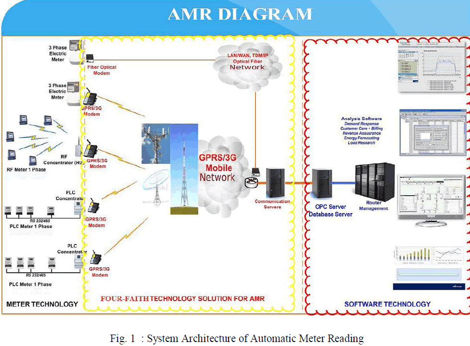
| Automatic Meter Reading System is a sophisticated system which allows companies to collect the readings without visiting the site. AMR include various technology for data collection such as power line communication, Zig-bee, Radio Frequency (RF Method) and GSM/GPRS network but GPRS network is best among this technology. So this paper will discuss only GPRS based AMR system. Automatic meter reading system helps the customer and energy service provider to access the accurate and updated data from the energy meter.AMR System can send energy consumption in hourly, monthly or on request. This data is sent to central system for billing and troubleshooting. These data are stored into the database server for processing and recording. By using this technique we can reduce the losses, labour cost, collection time, energy theft, avoids late payment. Adding to this it increases data security, improved customer service, reduced revenue losses. This system not only sends the data but also provides power disconnect/connect feature, power cut feature and tampering alert feature. |
LITERATURE SURVEY |
| AMR (Automatic Meter Reading ) is the modern Power measuring device that is used for measuring electricity , gas , water consumption in many countries on the world since it has a lot of advantages than that of the old analog meters doesn’t have . It has advantages in safety , real time measuring, accurate billing and time save as well as it has a better user interface and digital data analysis . |
| Based on communication systems, AMR has several types depends on measured data type and data transfer technologies. Nowadays AMR became the best solution to measure, collect and analyze data . The first generation of power meters was found which we know as (Watt-Hour meter ) [1]. As most of us know , the first generation(traditional meter reading devices ) is being used till now in many places .It has a lot of disadvantages, to overcome this disadvantages we have to modify a new reading system that provides remote reading , safety , on-time readings and a simple user interface. |
SYSTEM ARCHITECTURE |
| Automatic Meter Reading is the technology of automatically collecting data from energy metering device and transferring that data to a central database for billing and/or analysing. This saves employee trips and means that billing can be based on actual consumption rather than on an estimate based on previous consumption, giving customers better control of their use of electric energy consumption. The transmitter is connected to the meter and it counts the pulses from it and displays it over the seven segment display. It transmits the data over available communication media. |
 |
A. METER TECHNOLOGY: |
| Till now in India, many transmission protocols were introduced in terms of wired/wireless manner to read digital meters at remote places. In the present scenario the Digital watt-hour meters are based on microprocessors which replaced all the outdated electromechanical meters. In order to transmit the data Tele watt meters were implemented and they send the data to a remote central office through a dedicated telephone line and a pair of modems on monthly basis. To measure the consumption of electricity a microprocessor/DSP- based meter is used for multiple users in a residential area. A master PC is present at the control centre and it is used to send commands to the meters at remote ends, and it transmits the data back to the master PC, using the Power Line Communication (PLC) technique. Such techniques are mainly implemented in the areas with a fixed telephone network. Bluetooth energy meters were designed and implemented in some areas where they have several meters in close proximity ,with wireless communication interfaced to a Master PC. These meters are mainly designed for lower power consumption. As they are operating in a small range (power class- dependent: 1 meter, 10 meters, 100 meters) this technique is not effective enough and implemented only in areas with more population density. So a new method of using an energy measurement technique that combines the GSM network as a mean of transmitting energy data is more relevant. The GSM/GPRS networks are widely used in the developed and developing countries. This technique is very effective in rural areas, where most of the people do not have any access to a telephone network. So in a country like India we can implement this methods very easily and effectively. |
B.MODEMS: |
| The word modem comes from "Modulator-Demodulator" that defines the functions it performs. A Modem is a computer hardware used to transform the computer's digital data into analog data and vice versa. To communicate between distant computers over a network modems were used . |
| MODULATOR:It is the process of changing the digital form of a computer's signal to analog data which carries the information through telephone lines |
| DEMODULATOR: The process of coding back the modulated signal to be used by the computer. |
 |
| Fig. 2 : System Architecture of Modem |
| Modulator converts data from digital signal to analog signal at the transmitter side and again demodulator converts the same data from analog to digital format at the receiving end side. The process of converting analog data of one computer network to digital data of another computer network is referred to as digitizing. |
| Modems are usually used at both the ends when an analog signal is used for data communication between two digital devices called Data Terminal Equipment (DTE). DTE can be either a terminal or a computer. A modem is placed at the sending end it converts the digital signal which is generated by DTE into an analog signal by a modulating carrier. At the same time a modem is present at the receiving end, it demodulates the carrier signal and transmits the demodulates digital signal to the DTE. Any switched telephone circuit or a dedicated circuit can be used as a transmission medium between the two modems. If a switched telephone circuit is used, then modems are connected to the local telephone exchanges. For the transmission of data the modems are connected through telephone exchanges |
C.GPRS(General Packet Radio Service): |
| General Packet Radio Service (GPRS) is a packet-switching data that transfers the data globally through mobile networks of 3G and 2G cellular communication systems. It is a high-speed ,non-voice, and useful packet-based technology for GSM networks. |
| GPRS can be used to connect with other network based on Internet protocols which support a wide variety of commercial applications, as well as enterprises. We can send and receive compact and large data volume through mobile phone networks. Before sending the data, it is divided into individual packets and sent through the core network and radio. The data again reassembled at the receiver's end. |
| As mentioned earlier GPRS is not a completely separate network to GSM. Many of the devices such as the base transceiver stations and base transceiver station controllers are still used. Often devices need to be upgraded be it software, hardware or both. When deploying GPRS many of the software changes can be made remotely. There are however two new functional elements which play a major role in how GPRS works. The Serving GPRS Support Node (SGSN) and the Gateway GPRS support node (GGSN). These 2 nodes are new to the network with the other changes being small if any. Before explaining what these 2 new members of our network do it is important to ask how does the network differentiate between GSM (circuit) and GPRS (packet)? In simple terms there are in practice two different networks working in parallel, GSM and GPRS. In any GSM network there will be several BSC’s (Base Station Controllers). When implementing GPRS a software and hardware upgrade of this unit is required. The hardware upgrade consists of adding a Packet Control Unit (PCU). This extra piece of hardware differentiates data destined for the standard GSM network or Circuit Switched Data and data destined for the GPRS network or Packet Switched Data. |
D.SOFTWARE TECHNOLOGY: |
METER DATA ACQUISTION SYSTEM(MDAS): |
| Meter data acquisition system(MDAS), supply necessary hardware, software and communication equipment in the Substations, DTs and select consumers in the towns for the purpose of centralized meter data logging. The substation Data logger PC will acquire data from Feeder Meters and will transmit the same to Sub division office server through a GSM/GPRS Modem, whereas the Sub division office Data Acquisition server will acquire data directly from all Distribution Transformers as well as HT/select LT Consumers through GSM/GPRS Modems. |
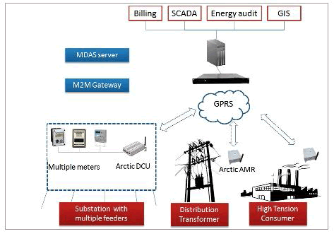 |
| Fig. 3 : System Architecture of Meter Data Acquisition System |
| The Data acquisition servers at all sub division offices shall push the entire meter data to central data centre on incremental basis during off-peak period on daily basis through MPLS/VPN based WAN network for data aggregation, analysis and generation of MIS report as per requirement of the utility. |
| The main objective is to acquire meter data from System and Select consumer meters automatically from remote avoiding any human intervention, Monitor important distribution parameters, use meter data for accurate billing purposes and generate exceptions and MIS reports for proper planning, monitoring, decision support and taking corrective actions on the business activities by the management. The above objective under this specification is achieved by providing an Automatic Meter Reading (AMR) based Data Logging System using any of the available Communication Technologies like GSM, GPRS or Low Power Radio covering all the Feeder Meter, DT Meters and select Consumer Meters in the entire Utility area. |
DEVICE LANGUAGE MESSAGE SPECIFICATION[DLMS]: |
| Device Language Message Specification (DLMS) is comparable to a set of rules or a common language, on which the various operators have agreed. The DLMS-protocol enables the integration of energy meters with data management systems from other manufacturers. Companion Specification for Energy Metering (COSEM) is an interface model of communicating energy metering equipment, providing a view of the functionality available through the communication interfaces. The DLMS/COSEM specification specifies a data model and communication protocols for data exchange with metering equipment[5]. |
| Demand Side Management needs universal definitions and communication standards. DLMS – COSEM is basically the common language between the partners that provides to communicate with each other. |
| An object model, to view the functionality of the meter, as it is seen at its interface. |
| An identification system for all metering data. |
| A messaging method to communicate with the model and to turn the data to a series of bytes. |
| A transporting method to carry the information between the metering equipment and the data collection |
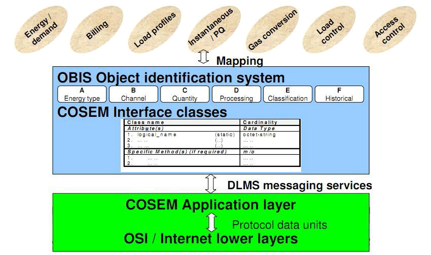 |
| Fig. 4 : System Architecture of DLMS |
SYSTEM WORK FLOW |
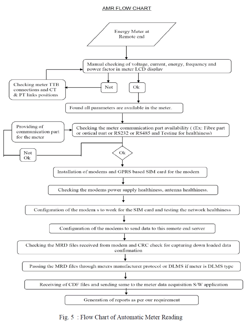
| Large amount of data must be retrieved from the remote meters on a regular and scheduled basis. For that we have to check the voltage, current, frequency and power factor in meter LCD display manually. If all the parameters are available in the meter then we have to check the communication part. Then we have to install the modem with GPRS based SIM. Configure the modem to work for the SIM card and check the network healthiness. Configure the modem to send data to the required remote end server. Check the MRD files received from the modem and check for capturing down loaded data confirmation. Then pass the MRD files through the DLMS protocol. After receiving the CDF files, send the same files to the MDA software application to generate the reports. Using MDA software, we can the detail view of the meters regarding the selected town. The DLMS protocol is used for collecting the particular details of the town which we select. |
 |
SOFTWARE IMPLEMENTATION: |
| Here we use MDAS application to capture the reading from remote end. The following steps are to done to monitor the readings. |
| STEP 1: Login to the website |
| Example: User Name: |
| Password: |
| Click on “Sign In” Button to login. |
| STEP 2: After successful login, the home page is displayed. In the home page, select the details for the drop downs provided and then click the search button. |
| STEP 3: To get the details of a EH, select EH in the home page filter. Then select details from the drop-down list and click on search to view the detailed list. |
| STEP 4: To view the details of a town, select Town in the home page filter. Then select town details from the dropdown list and click on search to view the result. |
| STEP 4.1: Select and double click on any of the connection to get the Voltages & currents at this instant of time. |
| STEP 4.2: Click on the meter details to know about the Geographical hierarchy & Electrical hierarchy and DTR Location. |
| STEP 4.3: Click on the Energies tab to know the Energies History including the Current month. The user can view Active Energy(kWH), Apparent Energy(kVAH),Reactive Energies both Lag & Lead[kVARH(lg)/kVARH(ld)). |
| STEP 4.4: Click on the Demands tab to get the kVA & kW Demand with Date of Occurrence, frozen in meter memory at every month Mid night at 00:00hrs. |
| STEP 4.5: Click on the Load survey data to get the Energy consumption data for every half an hour. The user can view Active Energy, Reactive Energy, Apparent Energy. |
| STEP 4.6: Click on the “Tampers” tab to get the tampers recorded in the meter, with tamper description, voltages & currents with tamper occurrence time & tamper restoration time. |
| STEP 4.7: Click on the “Reports” tab to view the reports for voltages, currents, Energies, Load Survey data, Miscellaneous data like Power factor & Phase angle, Tamper data & day wise billing. |
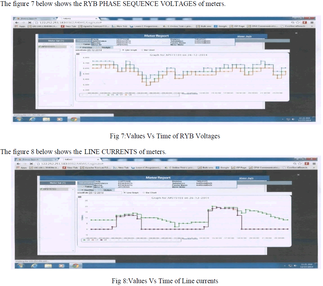
| STEP 4.7.1: Enter the Start date & End date and click on the “Get Data” button to get the voltages for all the three phases between the selected range. Graph is plotted based on the data obtained. |
| STEP 4.7.2: Enter the Start date & End date and click on the “Get Data” button to get the Currents for all the three phases between the selected range. Graph is plotted based on the data obtained. |
| STEP 4.7.3: Enter the Start date & End date and click on the “Get Data” button to get all the three types of Cumulative Energies(displayed in meter) between the selected range. Graph is plotted based on the data obtained. |
| STEP 4.7.4: Enter the Start date & End date and click on the “Get Data” button to get the Load survey data between the selected range. Graph is plotted based on the data obtained. |
| STEP 4.7.5: Enter the Start date & End date and click on the “Get Data” button to get all the three phase angles between the selected range. Graph is plotted based on the data obtained. |
| STEP 4.7.6: Enter the Start date & End date and click on the “Get Data” button to get the Tamper data between the selected range |
| STEP 4.7.7: Enter the Start date & End date and click on the “Get Data” button to get the Last Monthly billing data. |
RESULTS |
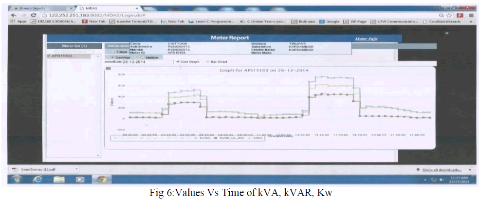
| The figure 6 below shows the APPARENT POWER(kVA), REACTIVE POWER(kVAR), ACTIVE POWER(kW) of meters. |
 |
 |
CONCLUSION |
| This paper has proposed an AMR system with the combination of GPRS, focusing on collecting the readings from the remote end. Using the AMR, the data of meter devices are read and transferred to the remote end on time for further analysis. By using this system we can overcome the losses like power theft, improper metering. Multiple transceivers used in automatic meter reading system incorporate no data loss. From this proposed method it can be concluded that automatic meter reading system can be really proved as a boon for consumers and electricity board. The data collection and manipulation task becomes fast and easier. Any modification can be made to the code in less time. Changes in rate or unit calculation can be done very effectively. |
References |
|