ISSN ONLINE(2278-8875) PRINT (2320-3765)
ISSN ONLINE(2278-8875) PRINT (2320-3765)
Jing Hu1, Lujie Yu2, Zhongwei Zhang3, Jin Lu4
|
| Related article at Pubmed, Scholar Google |
Visit for more related articles at International Journal of Advanced Research in Electrical, Electronics and Instrumentation Engineering
Multi-Terminal Direct Current transmission system based on Modular Multilevel Converter(MMCMTDC) has great application prospects on power transmission away from load centre, renewable energy transmission, distributed power transmission and the multi-grid interconnection. A voltage margin control scheme is designed for MMC-MTDC system; and a detailed mechanism analysis of the monopole ground fault and bipolar short-circuit fault of the MMC-MTDC is carried out on the DC cable faults. Using PSCAD / EMTDC, a three-terminal DC transmission system is built to proof the effect of control and protection schemes for DC cable faults in MMC-MTDC system. The simulation results show that thanks to the control and protection schemes, the multi-terminal DC transmission system under the faults can achieve fast recovery based on quick DC switches after a system failure. Moreover, the power transmission requirements are well met, and the stability of the system is effectively improved.
Keywords |
| Modular Multilevel Converter (MMC), Multi-Terminal Direct Current (MTDC), DC Cable Fault, Coordinated Control, Control and Protection Schemes |
INTRODUCTION |
| Modular Multilevel Converter (MMC), with a low switching losses and less demanding of device identity, is a new type of Voltage Source Converter (VSC) topology, which has great development potential in high-quality and highcapacity HVDC transmission system [1]. MMC structure is used in multi-terminal DC transmission system, which composes multi-terminal direct current based on MMC (MMC-MTDC). MMC-MTDC can give full play to the engineering and technical advantages of the MMC, meanwhile it can take into account the economy, flexibility and controllability of MTDC system [2]. It is suitable for variety of occasions such as: remote power supply, isolated island transmission, decentralized distributed power transmission, local power transmission to islands, as well as multi-grid interconnection. At present, Zhoushan 5-terminal project under construction in China and Nanao flexible HVDC project in China will become the first MMC-MTDC projects in the world. |
| Due to the special structure of the MMC, the fault characteristics of MMC-HVDC system are different from two-level VSC-HVDC. On the other hand, compared to the two-terminal system, the control and protection policy and protection timing of multi-terminal MMC-HVDC system are more complex, because it need to make sure the new system of nonfault- terminal can keep on running after the failure with the coordinated strategy between stations. In [3], DC line failure mechanism of two-terminal MMC-HVDC system is analysed, but it takes the ideal resistance model as DC transmission line. In fact, cables are more general used in practical MMC-HVDC projects, and the DC fault will show different characteristics due to the different line model. A MMC-MTDC system model is built in [4], and simulation analysis of the control characteristics and system behavior under the DC fault is given, but it did not provide specific control and protection strategies. |
| Research on DC cable faults in MMC-MTDC system can provide an important theoretical basis for MMC-MTDC projects. In this paper, a double voltage margin controller is designed for MMC-MTDC system at first, and then monopole ground fault and bipolar short-circuit fault of MMC-MTDC are analysed in detail, and the control and protection strategies are proposed. At last, three-terminal DC transmission system based on 21-level MMC is established in PSCAD environment to verify the effectiveness of the proposed control and protection strategies. |
STRUCTURE AND OPERATING PRINCIPLE OF MMC-HVDC SYSTEM |
A. The Topology and Sub-Module Structure of MMC |
| The topology and the sub-module structure of MMC are shown in Figure 1. MMC converter valve is constituted by six arms, and each arm is composed by several sub-modules which are connected with each other and a reactor L0 in series [5]. |
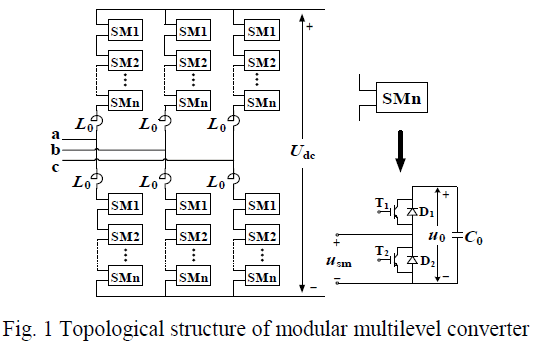 |
| The MMC sub-module consists of a IGBT half-bridge (including two IGBTs of T1 and T2 ;two anti-parallel diodes of D1 and D2) and a DC energy storage capacitor (C0). Each sub-module is a device of double ends, and it can switch between the full module voltage (T1 = ON, T2 = OFF) and zero module voltage (T1 = off, T2 = ON) at the cases of the two current directions. To adjust the voltage of the converter bridge arm, the inputting quantity of the sub-module of the commutation bridge arm is selectively controlled. |
B. The Operating Principle of MMC-HVDC |
| As the MMC bridge output voltage is determined by the number of the switched sub-modules on the bridge arm, so the MMC bridge output voltage can be equivalent to a controllable voltage source [6], the single-ended three-phase equivalent circuit of MMC-HVDC is shown in Figure 2. U1 is the phase voltage of the AC system grid node (PCC); k is the ideal transformer ratio, usiïüÃËi=aïüÃÅbïüÃÅcïüÃâ°is the output voltage at the secondary side of three-phase AC ideal transformer, R represents the equivalent resistance of the loss of lines and transformers, LT represents the leakage inductance of converter transformer; ui is the output voltage value of the MMC, iiïüÃËi=aïüÃÅbïüÃÅcïüÃâ°is the three-phase AC current value at the grid-side of the converter; L0 is the inductance value of the bridge arm reactor, uip and iip are respectively the three-phase voltage and current of the upper arms; uin and iin are the lower arm voltage and current of three phases; idc is the DC current; Udc is the DC voltage; point N is the potential reference point of the AC neutral point, point O is the equivalent zero potential point at the DC side, of which at least one must be connected to the ground. |
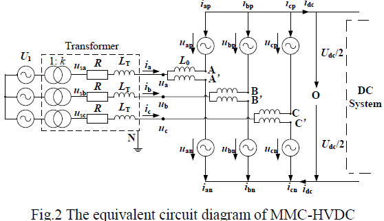 |
| Take the phase A as example, in the figure the potential difference voltage of points A and A' with point O are uAO and uA’O. If ignore the circulation of the three-phase bridge between the arms, bridge arm voltage of phase A is as follows: |
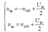 |
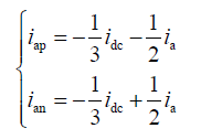
| Where, the point A and A' are isoelectric. On account of the strict symmetry of three phase unit cells as well as the upper and lower bridge arm in MMC, the DC current idc is divided equally among the three phase unit cells, and the output current of phase A in the upper and lower leg are divided into two parts. Therefore, the current of phase A in the upper and lower leg are as follows: |
 |
COORDINATED CONTROL METHOD AMONG MULTI-TERMINAL STATIONS AND THE CONTROLLER DESIGN |
A. Coordinated Control Method among Multi-Terminal Stations |
| Coordinated control method among stations is particularly important in MTDC system. In addition to achieving the basic functions of each station, the control method should coordinate all the stations in the system, taking appropriate control strategy with flexible and smooth switch according to different operating modes while different disturbance or overhaul is happening in the system, where the advantage of system reliability in MTDC is reflected. For the parallel MTDC system, the core of control target is maintaining a constant DC voltage and the power balance. |
| The single-point DC voltage control (also called a master-slave control [7], [8]) is used in early studies. Only one station is responsible for controlling the DC voltage, while the remaining stations respectively control the DC current or active power for their own. However, when the station controlling DC voltage suffers a failure from AC or DC side, it may be taken out of operation or changed to control DC current or active power. As a result, the entire MTDC system loses the ability to regulate the DC voltage. Therefore, for the parallel MTDC system, it is essential to take a multipoint DC voltage control, as there are more than two stations in the system able to control DC voltage. At present, there are two main methods for multi-point DC voltage control in parallel MTDC system. They are voltage drop characteristics control [9] (also called decentralized coordinated control) and voltage margin control [10], [11] (also called improved master-slave control). The former control method is flexible and simple, but it will produce a big DC voltage deviation when there are large power disturbances. While the voltage margin control can pull a certain margin between the master and slave stations. It has good control characteristics, able to switch control strategies fast and automatically when there are large disturbances. |
B. Double Voltage Margin Control |
| In this paper, a double voltage margin control method is presented based on the general voltage margin control for the MTDC system. The system voltage-power characteristic of double voltage margin control is shown in Figure 3. |
 |
| Operating point of each station should be located inside the operating scope limited by the dashed rectangle. Station 1 is the master station. Normally the master station is connected with a stronger AC system, and has a wider range of power adjustment. Station 2 is a slave station; voltage margin control is used in this station. There are two different margins between the slave station and master station’s reference DC voltage value, respectively the positive voltage margin and the negative voltage margin. An active power control is used in station 3, stabilizing the output power at the power reference value. If station 3 is connected with a passive system, only a AC voltage control is needed, in which way the control characteristics resembling the active power control, but the vertical line of power reference value will have a translation when the load changes. |
| As shown in Figure 3, when the three-terminal system operates in the normal state, DC voltage control is used in station 1, while active power control is in station 2 and station 3. The MTDC system operates stable at point A. |
| When the demand for active power increases (as shown by the dotted line) in station 3, the power balance in the system will be maintained by increasing the output power of station 1. If the output power of station 1 reaches the limit, the system will operates to point B; station 1 will not be able to adjust DC voltage. If the power balance can not be reached at point B yet, the system will not be stable any more. The DC voltage will drop, and another station is needed to replace station 1 undertaking the task of regulating DC voltage and power-sharing. Therefore, control method of station 2 will be changed from active power control to DC voltage control. The operating point of the system will move from B to C. At the same time, control method of station 1 will be changed from DC voltage control to active power control. If station 1 is out of operation for some reason, such as a failure happens, control method of station 2 can be changed from active power control to DC voltage control, while the operating point of the system will move from A to D. |
| Likewise, if the demand for active power of station 3 reduces suddenly, or even a power inversion is needed, or station 1 operated as an inverter before dropping out, it is possible that the operating point of station 2 will reach to UdrefH. Thus, compared with single voltage margin control, double voltage margin control can meet more demand under the same controller complexity. Controller structure for double voltage margin control which can achieve the characteristic shown in Figure 3 is shown in Figure 4. |
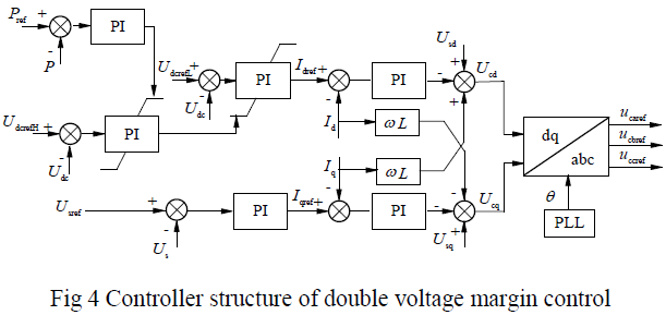 |
| As shown in Figure 4, this controller combines the positive voltage margin DC voltage controller, negative voltage margin DC voltage controller, and the PI output and limit values of active power controller. When the limit is not reached, the controller maintains the active power. While the limit is exceeded, the controller changes to DC voltage control automatically. |
DC CABLE MECHANISM ANALYSIS IN MMC-MTDC |
| For MMC-MTDC system, the dc-link fault is one of the most serious faults .When the dc-link fault is a transient failure, it’s hoped that it can recovery quickly with the help of the control system. When it is a permanent fault caused by mechanical stress, it is necessary to block the converter, and then open the circuit breaker. Because of the different topologies, the dc-link fault mechanism analysis and the protection in MMC-MTDC are distinct from those of the 2- level VSC-HVDC system. It should be taken into consideration that after the clearance of the faulted line, the rest of systems can restart efficiently. |
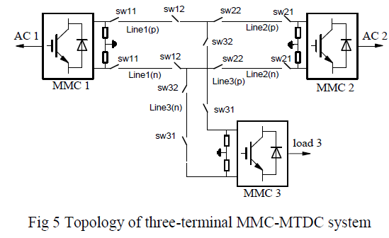
| Both overhead lines and cables can be used in MMC-MTDC system. DC cable faults are usually caused by digging away or anchor force. Monopole fault and bipolar fault are likely to happen, each of which is a permanent fault. This paper focuses on the DC cable faults, and analysis the MMC-MTDC monopole fault and bipolar fault. Because the availability of a DC circuit breaker whit HV and large current is limited, MMC-MTDC only use the fast DC switch to isolate the fault line. The topology of a three-terminal MMC-MTDC system is shown in Figure 5. |
A. DC Cable Monopole Fault Mechanism Analysis |
| The DC capacitor of MMC-HVDC is located in the sub-module. As a result, the fault features are different from those of 2-level VSC-HVDC. The arm current of MMC consists of capacitance discharging current and the AC system current, as shown in Figure 6. |
 |
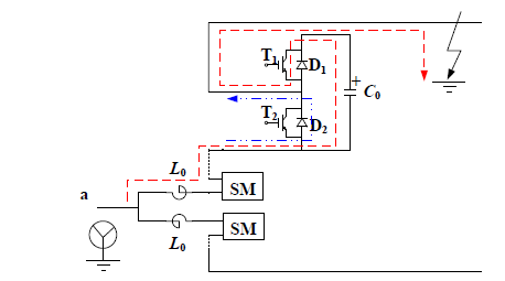 |
| Fig 6 Path of injection short-circuit current from AC grid to MMC for monopole fault |
| When the converter side of transformer is star grounding, AC ground point and the point of failure constitute a pathway, the AC side and the sub-module capacitor current will be injected to the point of failure, which will reach the peak in the half frequency cycle .After blocking the converter, the AC side current will continue injecting to the point of failure through diode D2.which is still higher than the rating current. |
| When the converter- side of the transformer is the delta connection, there is no pathway for AC side current and the sub-module capacitor discharging. Therefore, after the failure direct current will fluctuate in a minor range, and then maintain it in rating value. The simulation model in this paper is using Y0/delta wiring. |
B. DC Cable Bipolar Fault Mechanism Analysis |
| The bipolar fault in MMC-HVDC system is most serious, the fault current of MMC consist of capacitance discharging current and the AC system current [12]. After the fault, sub-module capacitor voltage and DC voltage decreases rapidly to zero, power transferring to the inverter will terminate. As for AC system, it is the same as three-phase fault. The Path of injection short-circuit current from AC grid to MMC for bipolar fault is shown in Figure 7. |
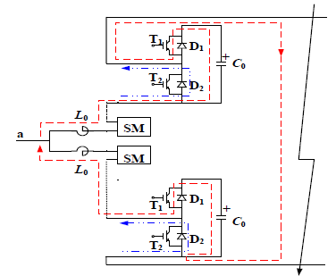 |
| Fig 7 Path of injection short-circuit current from AC grid to MMC for bipolar fault |
SIMULATION ANALYSIS |
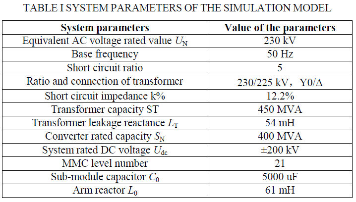
| A 3-terminal MMC-MTDC simulation model is established in PSCAD/EMTDC and the system structure is shown in fig.5. The parameters of the model are shown in table 1. In steady state, station 1 adopts constant DC voltage control and the reference value is 400kV, station 2 adopts constant active power control and the reference value is -200MW, station 3 adopts constant active power control and the reference value is -150MW. |
 |
A. Single-Pole to Ground Fault of MMC-MTDC |
| Supposing the positive pole of line1 near to station 1 occurs metal grounding permanent fault at 2s and the grounding resistance is 10 mΩ, the simulation waveforms are shown in Fig.8. |
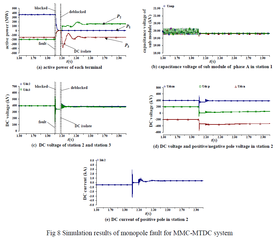 |
| As shown in Fig.8(d), during the fault, the potential reference point of the DC side is changed, for the clamping resistance parallel connection on the DC side and the constant DC voltage control, the positive pole voltage Udcp decreases to 0 and the negative pole voltage Udcn increases to twice of the initial value, the pole-to-pole voltage Udc keeps constant. The DC voltage offset phenomenon exists even though the fault is cleared owing to the charging effect of the cable capacitor. This will be a great threat for the insulation voltage of the cable, thus the insulation of the cable and AC bus of the converter should be designed reasonably. As shown in Fig.8(b), capacitor voltage will keep constant because there isn’t a charging path between the capacitor and the grounding point. |
| The cable fault is usually permanent fault, so the fault cable should be isolated as soon as possible. The AC side of the converter isn’t connected to ground; as a result, the large fault current won’t appear in DC side. In the simulation the 3 converters will be blocked after 10ms (at 2.01s) and the DC current will decrease to 0, the simulation is shown in Fig.8(e). at this time, the AC breaker needn’t be tripped, a DC quick switch can be adopted to disconnect the fault line, the DC quick switch SW12 and SW12 of line1 are disconnected after 80ms(at 2.08s)ïüÃÅ at 2.09s the converter2 and converter3 are deblocked. The results are shown in Fig.8(a) and Fig.8(c). With adopting DC voltage margin control, control mode of converter 2 will transformed from constant active power control to constant DC voltage control and will be responsible for the power balance and voltage stability of the new system consisted of the rest terminals without faults. |
B. Pole-to-pole short-circuited fault of MMC-MTDC system |
| Supposing that a pole-to-pole short-circuited fault occurs to the DC line 1, the simulation results after adopting corresponding protection schemes are shown in fig.9. |
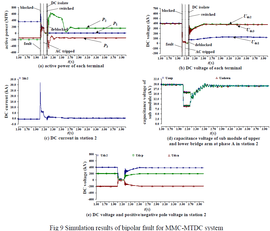 |
| When the fault occurs, sub-module capacitor will be discharged quickly through T1 and the AC side will feed fault current through D2, which results in DC current surging (shown in Fig.9(c)), this will result in over current of submodule capacitor and relevant IGBT and diodes, so the over current should be considered when designing. When the pole-to-pole fault is detected, converters of all the terminals will be blocked in 10ms, sub-module capacitors will be charged through diode D1 and there isn’t a charging path, but AC short-circuit current can still be fed through D2 into the fault point. So at 80ms after the fault all the AC breakers will be tripped to break the AC current in-feed, at this time arm current will be provided by the freewheeling of the reactor, with the releasing of the energy of the arm reactor, arm current decreases to 0 gradually. After the arc extinguishing the quick DC switch of the two terminals of the fault line, thus the fault line will be isolated and the station MMC1 will stop operating. Then the rest converters will restart, with the DC voltage margin control scheme, control mode of MMC2 will be transformed from constant active power control to constant DC voltage control and the rest system will keep balanced, the simulation results are shown in Fig.9(a) and Fig.9(b). As shown in Fig.9(d), capacitor voltages of station 1 will keep at the value when being blocked and capacitor voltages of station 2 will restore to the normal value after the converters are deblocked. The pole-to-pole short-circuit fault is symmetric fault, so the DC pole-to-pole voltage keeps at 0 during the fault and restores to the normal value after the system recovers, the DC voltage offset when single-pole-to-ground fault occurs. |
| The timing sequence of the protection after pole-to-pole fault occurs is as follows: converters of the 3 terminals are blocked at 2.01s, AC breakers of the 3 terminals are tripped at 2.08s, the quick DC switch of line 1 is tripped at 2.15s, the AC side of station 2 and 3 is switched on at 2.16s, the station 2 and station 3 re-start at 2.17s. |
CONCLUSION |
| Based on the operation principle and the mathematical model of MMC, a suitable double voltage margin coordinated control strategy is designed for MMC-MTDC system. Then DC cable faults in MMC-MTDC system, include the monopole ground fault and bipolar short-circuit fault, are researched by detailed mechanism and simulation analysis. Without considering the DC circuit breaker, control and protection schemes are given against the DC cable faults. Simulation results show that, using coordinated control method based on the voltage margin control, with the corresponding protection action sequence, fault line and the connected converter station can be quickly isolated, which reduces the influence from fault current and voltage to the device, and make the remaining non-fault line and converter stations restarted and continued to run. |
ACKNOWLEDGMENT |
| This wok is supported by National Natural Science Foundation of China (No. 51177042), National High Technology Research and Development Program of China (863 Program) (No. SS2013AA050105), and Fundamental Research Funds for the Central Universities (No. 12QX13). |
References |
|