International Journal of Advanced Research in Electrical, Electronics and Instrumentation Engineering
ISSN ONLINE(2278-8875) PRINT (2320-3765)
ISSN ONLINE(2278-8875) PRINT (2320-3765)
Ramesh Halakurki1, Ramesh Gollapalli2
|
| Related article at Pubmed, Scholar Google |
Visit for more related articles at International Journal of Advanced Research in Electrical, Electronics and Instrumentation Engineering
Resonant power conversion has many advantages over conventionally adopted pulse-width modulation, which are, low electromagnetic interference, low switching losses, small volume, and light weight of components due to a high switching frequency, high efficiency, and low reverse recovery losses in diodes results to a low di/dt at switching instant. So, this resonant converter is used for direct current (dc)-to-dc energy conversion applications. The proposed resonant converter topology comprises a half-bridge inductor-capacitor-inductor (L-C-L) resonant inverter and a diode bridge rectifier. Then, the output stage of resonant converter is filtered by using low-pass filter. The measured energy conversion efficiency of the resonant converter reaches up to 88.3%. Capacitor-inductor-capacitor(CL- C) resonant converter is more preferable than the L-C-L resonant converter; because of, it improves the energy conversion efficiency and also reduces the equipment cost. The efficiency of C-L-C resonant converter is up to 93%. Moreover, test results demonstrate a satisfactory performance of the resonant converter. Furthermore, the proposed converter is highly promising for applications of power electronic productions such as switching power supplies, battery chargers, uninterruptible power systems, renewable energy generation systems, and telecom power supplies.
Keywords |
| Resonant inverter, diode bridge rectifier, L-C-L and C-L-C resonant tanks. |
INTRODUCTION |
| DC-DC converter is a class of power converters. It converts a DC source of certain level of voltage to another dc voltage level. And also, DC-DC converter can regulate the output voltage. Dc to dc converter are generally operates in two conversion methods; one is linear mode conversion and another one is switched mode conversion. Linear regulators can only gives the output at lower voltages from the input. Linear regulators are very inefficient when the current is high corresponding voltage drop is more and as they dissipate heat, that is equal to the product of the output current and the voltage drop; due to this reasons normally they are not used for large-drop high-current applications. Switched-mode DC to DC converter converts one level of DC voltage to another level, by storing the input energy temporarily at one voltage and then releasing that energy to the output at a different voltage. The storage may be in either magnetic field storage components such as inductors, transformers or electro static field storage components which are capacitors. This conversion method is more efficient than linear mode voltage regulation, up to 75% to 98%. This efficiency is very useful to increasing the running time or operation time of the battery operated devices. |
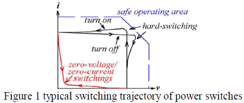
| In power energy conversion applications, switching power converter plays a significant role. These, direct current (dc)- to-dc converters are morally adopted in industrial, commercial, and residential equipment. Most of the inverters available now days in the market utilize the PWM (Pulse Width Modulation) technology. PWM based inverter technologies are most superior in many factors compared to other inverters designed by using conventional technologies. In practical analysis, in which the voltage across or current through the semiconductor switch is abruptly interrupted is termed as a hard-switched PWM. Hard switched PWM schemes have been largely adopted in modern power energy conversion applications, because of its simplicity and ease in control. |
| Higher switching frequency implies that the smaller and lighter weight inductors, capacitors and filter components of these converters. With an increasing of switching frequency, electromagnetic interference (EMI) and switching losses are increases, ultimately the efficiency and performance of dc-to-dc power converters are decreases. |
| To solve these above problems, some soft switching approaches must be operates under a high switching frequency. There are two commonly used soft switching methods, one is Zero voltage switching and other one is zero current switching schemes, in which either the voltage or current is zero during switching modes, which largely reduces the switching losses and Electro Magnetic Interference (EMI), these also increases power converters reliability. |
 |
| A soft switching dc-to-dc converter is constructs in cascading fashion a resonant dc-to-alternating current (ac) inverter, resonant tank and a bridge rectifier. The given dc input power is first converted into ac power by the resonant inverter, this ac power is then converted back into dc power by the rectifier. |
 |
| The energy is extracted from a resonant tank; resonant converters can be classified into three categories first is series resonant converter second is parallel resonant converter and final one is series-parallel resonant converters. The resonant inductor Lr and resonant capacitor Cr are in series. The major problems occurs in this series converter has light load regulation, high circulating energy and turn off current at high input voltage condition. The parallel resonant converter is formed with the combination of the capacitor and an inductor and another capacitor is placed across the diode rectifier converter. The major problems in parallel resonant converter has high circulating energy, high turns off current at high input voltage condition. In series parallel resonant converter, the resonant tank of this converter is equivalent to that of the parallel resonant inverter, except for an additional capacitor in series with the resonant inductor. This converter cannot operate safely with a short circuit at a switching frequency close to the resonant frequency and also energy conversion stage of this converter has not been minimized and simplified which results size and cost are more in the applications of dc-to dc energy conversion. From the above three different resonant converter topologies reveals that the parallel resonant converter is the optimum topology for dc-to dc energy conversion applications because of its many advantages including low switching losses, low stresses, and low noise characteristics. So, parallel resonant converter is generally recommended for the dc-to-dc energy conversion applications due to its simple circuitry and typical input characteristics. |
CIRCUIT DESCRIPTION AND OPERATING PRINCIPLES |
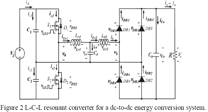
| Figure 2 shows the L-C-L tank resonant converter for a dc-to-dc energy conversion system, in these two capacitors C1 and C2 which are on the input side converter are large and split the dc input voltage into two halves. The elements Lr1, Lr2, and Cr are form the T-shaped resonant tank. The given dc input power is first converted into ac power by the resonant inverter, this ac power is then converted back into dc power by using the rectifier circuit. And the load resistance R is connected across a bridge rectifier across this low-pass filter capacitor Co connected to regulate the output. |
A. Circuit operating principles |
| The following analysis assumes that the converter operates in the continuous conduction mode, in which the semiconductors have ideal characteristics. Figure 3 displays the idealized steady state voltage and current waveforms in the proposed L-C-L resonant converter for a switching frequency fs that exceeds resonant frequency fo. Operating above resonance is preferred because the power switches turn on at zero current and zero voltage; thus, the freewheeling diodes do not need to have very fast reverse-recovery characteristics. |
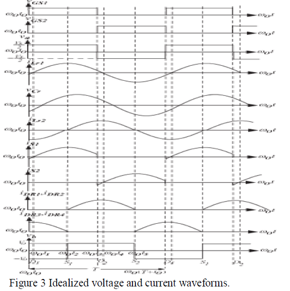 |
| Steady-state operations of the L-C-L resonant converter in a switching period can be divided into four modes. |
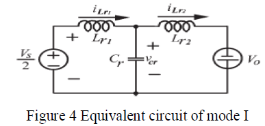
Mode 1-(Between ω0t0 and ω0t1): |
| The voltage appears across the resonant energy tank is in between +Vs/2 and −Vs/2 generates a square-wave voltage across the input terminal. The input voltage to the full-bridge rectifier is Vb when ilr2 (t) is positive and is –Vb when ilr2 (t) is negative. Before ω0t0, the active power switch S2 is conducts, and the current equals to the resonant tank current ilr1. When the power switch S1 is turned on at ω0t0, the resonant tank current ilr1 is negative and flows through freewheeling diode D1. At that instant ω0t1, resonant tank current ilr2 reverses and naturally commutates from freewheeling diode D1 to active power switch S1. Figure 4 shows the mode1 equivalent circuit of the L-C-L resonant converter. |
 |
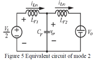
Mode 2-(Between ω0t1 and ω0t2): |
| This mode of operation is starts at ω0t1, when the current ilr1 resonant tank resonates from negative values to zero. At ω0t2, the switch S1 is forced to turn off, the positive current ilr1 is flows through the bottom freewheeling diode D2. Fig.5 shows the equivalent circuit of mode 2. |
 |
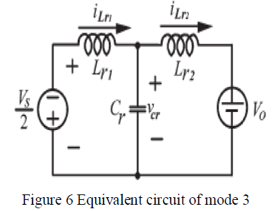
Mode 3-(Between ω0t3 and ω0t4): |
| This mode begins at ω0t3, when diode D2 is turned on, subsequently producing a resonant stage between inductors Lr1, Lr2 and capacitor Cr. Inductors Lr1, Lr2, and capacitor Cr resonate. Before ω0t4, gate pulse VGS2 excites active power switch S2. Figure 6 shows the equivalent circuit of mode 3. |
 |
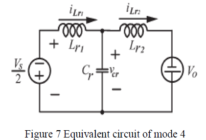
Mode 4-(Between ω0t4 and ω0t5): |
| Whenever the capacitor voltage ilr2 is positive, rectifier diodes DR1 and DR2 are turned on with zero-voltage condition at instant ω0t4. Figure 7 shows the equivalent circuit of mode 4. During the positive half-cycle of the inductor current ilr2, the power is supplied to the load through bridge rectifier diodes DR1 and DR2. During the negative half-cycle of the inductor current, the power is supplied to the load through bridge rectifier diodes DR3 and DR4. |
 |
OPERATING PRINCIPLE OF C-L-C RESONANT CONVERTER |
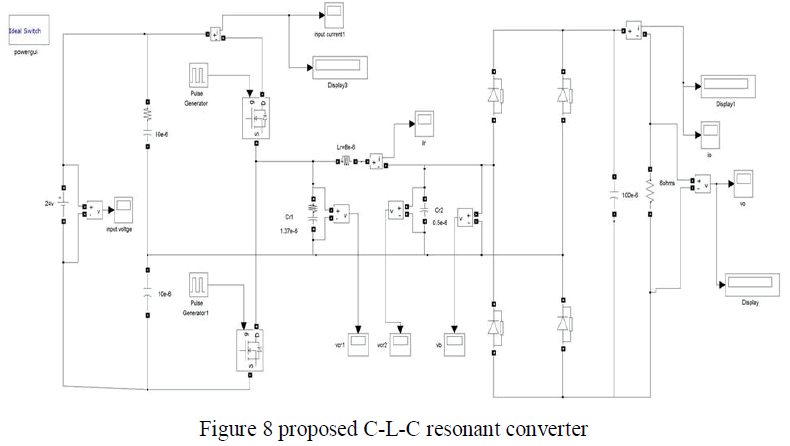
| Circuit description of C-L-C resonant converter is same as compared to the L-C-L resonant converter, only the difference is resonant tank. In case of Lr1-C-Lr2 resonant converter, the resonant tank is formed by connecting the components in T fashion, where as in Cr1-L-Cr2 resonant converter, the resonant tank is formed by connecting the components in ïÿýïÿý fashion as shown in figure 8. |
 |
| Like L-C-L resonant converter, the two capacitors divides the supply voltage into two halves and then the inverter circuit converts the given DC power into AC power, this can be given to the resonant tank. In resonant tank the storage devices stores the energy and then convert this AC power into DC power by using diode bridge rectifier and output can be regulate by using filter capacitor. |
OPERATING CHARACTERISTICS |
| The switching frequency of the active power switches is assumed to be greater than the resonant frequency so that the resonant current is continuous. Since the output voltage is assumed to be a constant Vo, then the input voltage of the bridge rectifier, Vb, is Vo when iLr2 is positive and is −Vo when iLr2 is negative. The resonant converter with a bridge rectifier stage for dc-to-dc energy conversion system is analyzed by considering the fundamental frequency of the Fourier series for the voltages and currents. The error due to this approximation is rather small when the switching frequency is higher than the resonant frequency. |
| Next, the output voltage Vb of the bridge rectifier can be described by a Fourier series as |
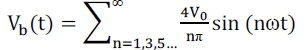 |
| The fundamental component of voltage Vb is |
| The current at the output of the bridge rectifier is the full wave rectified form of inductor current iLr2. Therefore, the average of the rectified inductor current |iLr2| equals output load current Io. If inductor current iLr2 is approximated as a sine wave of amplitude ILM1, the average value of output current Io is |
| The fundamental component of input current is |
| The value of output resistance in this equivalent circuit is based on the ratio of voltage to current at the input terminal of bridge rectifier. The resistance can then be defined as |
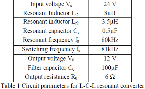
| The required component values of L-C-L resonant converter is described in below table1 |
 |
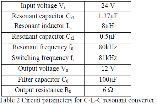
| The circuit parameters of the C-L-C resonant converter are shown in the table 2. Here C-L-C resonant converter is also operates same frequency but only the differences is in resonant tank components. |
 |
| Expression for resonant frequency f0 is obtained from the C-L-C resonant tank is |
| C-L-C resonant converter has more advantages when compared to the L-C-L resonant converter, which are the cost of L-C-L resonant converter components is less, size of the converter is also less. In L-C-L resonant converter two inductors are used, due to this the size of converter is large but in case of C-L-C resonant tank converter only one inductor is used to obtain the required output. Faster response is obtained in the C-L-C resonant tank converter and also efficiency of this converter is increased up to 93%. So compared to these two converters C-L-C resonant converter is best preferred. |
SIMULATION RESULTS FOR THE PROPOSED L-C-L RESONANT CONVERTER |
| A prototype was constructed and implemented in academic by taking many samples by varying inputs to demonstrate the effectiveness of the L-C-L resonant converter. The developed topology was connected to a 24-V dc source. Table I lists the circuit parameters for the proposed L-C-L resonant converter where the circuit simulations are also performed using MATLAB software in addition to this the resonant converter was implemented in practice and finally the simulation and practical results were compared with each other. |
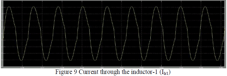 |
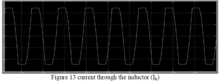
| The Figure shows the current through the inductor-1 (Ilr1) which is part of the component in L-C-L resonant tank the shape of this response is approximately sinusoidal. |
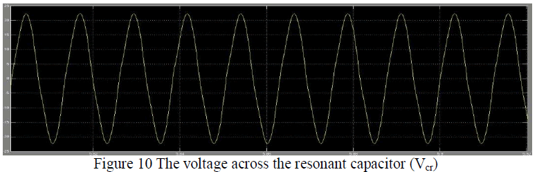 |
| The Figure 10 shows the voltage across the capacitor (Vcr) and the wave shape of this response is exactly sinusoidal |
 |
| Figure 11 shows the voltage across the inverter circuit or voltage across the input terminals of L- C-L resonant tank. |
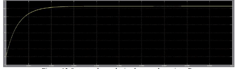 |
| Figure 12 Output voltage obtained across the resistor R0 |
| The above figure 12 shows the output voltage (V0) measured across the output resistor. The output of this converter is direct current so the wave shape is time invariant constant magnitude. |
SIMULATION RESULTS FOR C-L-C RESONANT CONVERTER |
| In place of L-C-L resonant tank is replaced by C-L-C resonant tank, then by observes the simulation results with practical values and compares with the above results. The performance characteristics of the inductors, capacitors and output voltage waveforms are obtained from the simulation. |
 |
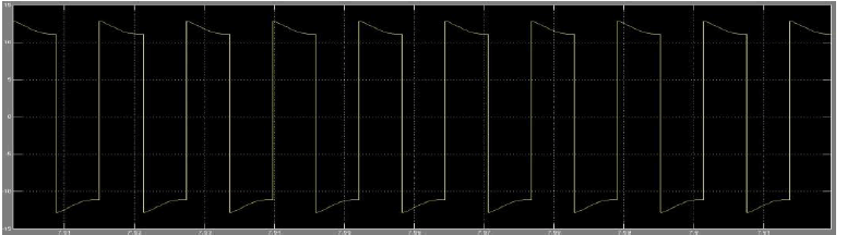
| The figure 13 shows the current through the inductor which is connected in between two parallel resonant capacitors and the shape of this wave form is in rectangular in nature. |
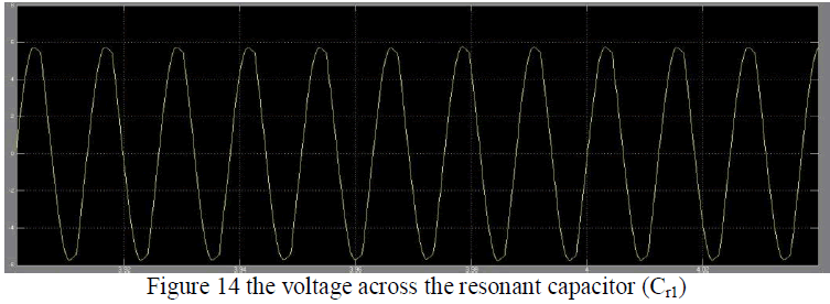 |
| The figure 14 shows the voltage across the capacitor which is connected at output of the resonant inverter that is input of the C-L-C resonant tank and the wave the shape is in sinusoidal in nature. |
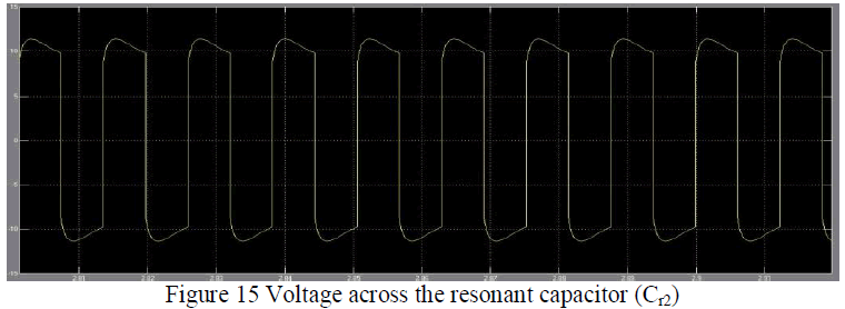 |
| The figure 15 shows the voltage across the resonant capacitor (Cr2) which is connected at output of the resonant tank that is input of the diode bridge rectifier. |
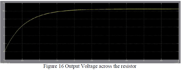 |
| The figure 16 shows the output voltage measured across the resistor (R0) which is connected at output terminals of the diode bridge rectifier and the shape of this wave form is unidirectional that means it has constant magnitude. |
CONCLUSION |
| This work develops L-C-L resonant converter and C-L-C resonant converter with a bridge rectifier for the application of dc-to-dc energy conversion. The L-C-L resonant converter structure is simpler and less expensive than conventional control mechanisms, which require many components. The L-C-L resonant converter topology is characterized by zero voltage switching, reduced switching losses, and increased energy conversion efficiency with the conventional converters. The output voltage/current can be determined from the characteristic impedance of the resonant tank by the adjustable switching frequency of the converter, where as the proposed resonant converter is applied to a load in order to yield the required output conditions. An experimental result gives the effectiveness of the proposed L-C-L resonant tank converter. The energy conversion efficiency in L-C-L resonant converter is 88.3%, which is quite satisfactory when the resonant circuit operating above resonance is applied to a dc-to-dc converter. In C-L-C resonant converter, reduces switching losses than L-C-L resonant converter and increase energy conversion efficiency up to 93%. An excellent performance is achieved at a lower cost and with fewer circuit components than with the C-L-C resonant tank converter with compared to the L-C-L resonant converter. |
References |
|