ISSN ONLINE(2278-8875) PRINT (2320-3765)
ISSN ONLINE(2278-8875) PRINT (2320-3765)
Mitesh Purohit1, Shailesh Khant2
|
| Related article at Pubmed, Scholar Google |
Visit for more related articles at International Journal of Advanced Research in Electrical, Electronics and Instrumentation Engineering
Microstrip Patch Antenna is generally used in modern communication devices. Study of past few year shows that, most of work on MPA is focused on designing compact sized Microstrip Antenna. As per Microstrip Patch Antenna offer low profile, low cost and low volume. But inherently MPA have narrow Bandwidth so to enhance bandwidth various techniques are engaged. This review paper shows some commonly engaged techniques to fabricate MPA.
Keywords |
| Multilayer,Multi Resonator, Modified Shape |
INTRODUCTION |
| A Microstrip Antenna in its simplest form consists of a radiating patch on one side of dielectric substrate and ground plane on other side. Microstrip Patch Antennas are popular for their well-known attractive feature, such as a low profile, light weight, and compatibility with Monolithic Microwave Integrated Circuits (MMICs). Modern Communication System, Such as those for satellite links (GPS, Vehicular, etc.), as well as emerging applications, such as Wireless Local Networks (WLAN), offer require antennas with compactness and low-cost, thus rendering planar technology useful, and sometimes unavoidable. Conventional microstrip patch antennas has some drawbacks of low efficiency, narrow bandwidth (3-6)% [1,2]of the central frequency, its bandwidth is limited to a few percentage which is not enough for most of the wireless communication system[3]. There are several designs have been investigated and reported to decrease the size of antenna [4] and to improve the bandwidth of antenna[5,6]. |
| Practically bandwidth of Microstrip Patch Antenna is narrow but, today wireless communication systems require higher operating bandwidth. Such as about 7.6% for a global system for mobile communication(GSM;890-960 MHz), 9.5% for a digital communication system(DCS;1710-1880 MHz), 5% for a personal communication system (PCS;1850–1990 MHz)And 12.2% for a universal mobile telecommunication system (UMTS;1920-2170 MHz) [7]. |
DEFINITION OF BANDWIDTH |
| The BW could be defined in terms of its VSWR or input impedance variation with frequency or in terms of radiation parameters. For the circularly polarized antenna, BW is defined in terms of the Axial Ratio [3]. |
| The VSWR or impedance BW of MSA is defined as the frequency range over which it is matched with that of the feed line within specified limits. The BW of the MSA is inversely proportional to its Quality Factor Q and is given by, |
 |
BANDWIDTH ENHANCEMENT TECHNIQUES |
| There are mainly four techniques for enhancement of Bandwidth of given Microstrip Patch Antenna. Which are given below, |
| 1. Multilayered configuration of Broadband MPA. |
| 2. Stacked Multiresonator MPA. |
| 3. Modified Shape Patch Broadband MPA. |
| 4. Planar Multiresonator configuration of Broadband MPA. |
| 1. Multilayered configuration of Broadband MPA. |
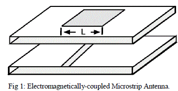
| In multilayered configuration patches are placed over different dielectric substrates and they are stacked on each other. Based on the coupling mechanism, these configurations are of two types electromagneticallycoupled or aperture-coupled [9].There are mainly two method of coupling to Multilayered antenna, |
| 1. Electromagnetically-coupled Technique. |
| 2. Aperture-coupled Technique. |
| Based on coupling Techniques they are classified. |
| In Electromagnetically-coupled Technique, If two-layered configuration of broadband microstrip patch antenna is analyzed then any one of them may be fed and other is electromagnetically coupled. Patch dimensions and dielectric constant of substrate may be different where as resonant frequency is closer to each other for obtaining broad bandwidth [11]. |
| This technique has the advantage that the dielectric constant of substrate used for microstrip feed line is high And it is thin so that radiation from feed line should be minimized, whereas the dielectric constant of substrate used for radiating patch is low and it is thick which improves the bandwidth of antenna [12]. |
 |
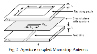 |
| Aperture coupled microstrip patch antenna as shown in figure (2) is also an indirect technique of exciting patch. In this configuration feed line is on lower side of ground plane which is having an aperture/slot, and is made up of substrate with high dielectric constant to reduce radiation losses. Whereas the top patch is made up of thick substrate with lower dielectric constant. |
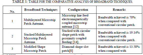
| Very high bandwidth can be generated by using multilayered configurations. Near about 70% bandwidth can be generated using multilayered configuration. Microstrip line feed electromagnetically coupled microstrip antenna [12] is a method of exciting the patch. Main disadvantage of this multilayered microstrip configuration is its increased height which is not desirable in miniature devices and in aperture coupling backward radiation is major problem [11]. |
| 2. Stacked Multiresonator MPA. |
| In this configuration multiresonator and stacked configurations are combined to provide broadband microstrip patch antenna. This antenna is applicable for wireless communication such as WLAN. A new novel stacked with circular shape patch is presented with wide impedance bandwidth of 19.14 % when compared with conventional circular patch antenna. The antenna structure is designed and simulated. Simulated results for return loss, impedance bandwidth and surface current distributions are discussed. Due to stack configuration of microstrip patch antenna it gives more impedance and width and size reduction is achieved through defected ground structure (DGS). |
| The proposed antenna is simple in structure with proximity coupled feeding can well feet for WLAN application [14]. |
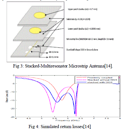 |
| Simulation of this antenna design is carried out in computer simulator technology (CST) to observe the performance of proposed antenna. Figure 4 shows the graph of simulated return losses. For stack configuration Without DGS, it has dual band with center frequencies 5.5 GHz and 6.5 GHz having impedance bandwidth of 9.8 % and 2 % respectively which is more than conventional circular patch antenna bandwidth of 3 to 4%. For stack configuration with DGS, it covers whole range of frequency from 5.3 GHz to 6.35 GHz band having impedance bandwidth of 18% or 1.05 GHz. |
| 3. Modified Shape Patch Broadband Microstrip Patch Antenna |
| In this technique bandwidth enhancement is done by changing/modifying the shape of radiating patch. It is found that some shapes of patches have lower Q factor as compared to other therefore having high bandwidth [7].These patches shapes include annular ring, rectangular/square ring, shorted patch and other geometries. There are several designs of broadband microstrip patch antenna with modified patches. A design of broadband circular patch microstrip antenna with Diamond shape slot is given by Garima, et al. [8]. In this paper a circular patch microstrip antenna having a concentric diamond shape slot is presented. Its configuration is shown in figure (4). |
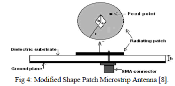 |
| This antenna is applicable for C-band. Substrate used in this antenna is FR-4 and produces the bandwidth of 13.58% when compared with conventional circular patch |
| 4. Planar Multiresonator configuration of Broadband MPA. |
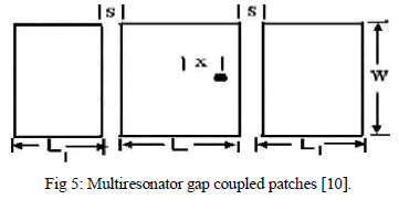
| In such configuration of microstrip antenna multiple resonators are placed near to each other, only one is fed and others are parasitically coupled, it is also known as gap coupling. Another way used to feed multiresonator configuration is to directly connect the patches via microstrip line. In some cases hybrid coupling is also used which include gap and direct coupling [12]. Design of Bandwidth Enhancement of Microstrip Antennas Using Shifted Parasitically Coupled Planar Multiresonators is given by K. Chattopadhyay et al. [10]. Proposed design is shown below in figure (3). In this paper, a wideband planar multi resonator antenna with parasitic coupling is proposed. Results show gradual improvement in impedance bandwidth from 65 MHz to 251 MHz (about four times) with very minor variation of resonance frequency from 2.989 GHz for reference patch to 3.023 GHz for anticlockwise shifted parasitically coupled elements. G. Eason, B. Noble, and I. N. Sneddon, “On certain integrals of Lipschitz-Hankel type involving products of Bessel functions,” Phil |
 |
 |
 |
CONCLUSION |
| This paper shows the review and survey of various Bandwidth enhancement techniques of Microstrip Patch Antenna. By using one of any above mentioning techniques Bandwidth of Microstrip Patch Antenna can be improved significantly which will overcome limitation of Microstrip Patch Antenna such as narrow Bandwidth. Out of all mentioned techniques Multilayered Technique yield maximum bandwidth. |
References |
|