Research & Reviews: Journal of Engineering and Technology
ISSN: 2319-9873
ISSN: 2319-9873
Department of Naval Architecture, Ocean and Marine Engineering, University of Strathclyde, Glasgow, G4 0LZ, UK
Received Date: 06/06/2017; Accepted Date: 19/06/2017; Published Date: 26/06/2017
Visit for more related articles at Research & Reviews: Journal of Engineering and Technology
In this study, an overview of the research methods used for straight blade Vertical Axis Turbine (VAT) has been presented. Up to date parameter studies on straight blade VAT have been reviewed. An in-depth discussion on each parameter in terms of the influence on the energy extraction efficiency is provided. Finally, the summary of the review and gaps found for future research have been discussed
Vertical axis turbine, Research methods, Parameter studies
Renewable energy devices plays an important role in the modern society. They provide clean and sustainable energy to industry and people’s daily life which is an ideal replacement of the traditional fossil fuels. Among all renewable energy devices, tidal/wind turbines are one of the most popular types. Classic tidal/wind renewable turbine have been classified into two general types, i.e., Horizontal Axis Turbine (HAT) and Vertical Axis Turbine (VAT) based on its installation and operation features.
A HAT is a type of energy turbine whose main rotor shaft is horizontally installed. The blades, shaft and generator must be installed on a tower and the rotating disk must towards the fluid flow to reach the maximum extraction efficiency [1]. HAT is commonly been used in the modern renewable industry as it has already been well developed. The working tip speed ratio for a typical HAT is around 6.0 to 18.0 depending on its blade numbers. The peak power coefficient could reach up to 0.48.
The rotor shaft of a VAT is been vertically installed. There are many special features of a VAT compared with a HAT. The blade of a VAT is much simpler than a HAT. Since the VAT operates vertically, therefore, it doesn’t need to face towards the flow direction. A VAT is also non-sensitivity to the water depth for tidal or water current applications. The working tip speed ratio for a typical straight blade VAT is smaller than that for a HAT and the peak power coefficient of a typical straight blade VAT is also lower than that of a HAT. Therefore, it is necessary for the modern industry to study and optimize the VAT, to enhance its efficiency [2,3].
The use of vertical axis turbines can be dated back to 2000 years ago. The first description on the use of VAT was in a Chinese book in 1219 [4]. Savonius invented the first modern drag driven vertical axis turbine in 1929 [5]. In 1931, French engineer Darrieus invented and patented both troposkien and straight blade vertical axis turbines in the U.S [6]. In the 1970s, Canada and America conducted several investigations into the power prediction using experimental and numerical methods [7-10]. Many improvements have been achieved in the vertical axis turbine by past researchers since then. However, the energy extraction efficiency of VAT has not been sufficiently high until now. Modern VAT can be grouped into two categories based on the source of the rotating moment. One of them is drag driven turbines; the other is lift driven turbines. The drag coefficient of the drag driven turbine blade, which moves towards the incoming flow, should be much larger than that of other blades in the same turbine, so the rotating moment can be generated [4]. The drag driven vertical turbine has a good performance at the small tip speed ratio. Its peak efficiency is around 15%. The blade of a lift driven vertical turbine usually has a cross section of airfoil. It can generate a rotational moment by the lift force of the blade. The working tip speed ratio and the peak efficiency are all higher than that of a drag driven vertical axis turbine. The lift driven turbine contains a curved bladed type (such as a troposkien shape) and a straight bladed type based on the shape of the blade. A straight bladed type is much simpler in terms of manufacturing but has a larger bending stress than that of the curved bladed. In the present paper, the straight blade lift driven vertical axis turbine is mainly focused on.
In the rest of the paper, key parameters of VAT are listed in Section 2. The research methods used in VAT studies are presented in Section 3. Parameter studies for VAT aimed to optimize and enhance its energy extraction efficiency are reviewed in Section 4. Lastly, a summary of the findings and gaps is in Section 5.
Several key parameters which quantify the turbine energy extraction performance are described below.
The performance of a VAT is highly depend on the rotational speed. The non-dimensional parameter tip speed ratio λ is to quantify the linear velocity of the VAT blade tip with the incoming flow velocity:
 (1)
(1)
where ω is the angular velocity of the turbine, R is the turbine radius, U is the velocity of the incoming flow.
The blade moment coefficient cm is defined as:
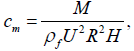 (2)
(2)
where M is the blade moment relative to the turbine pitch centre, ρf is the fluid density, H is the height of the turbine blade.
The power coefficient cop is determined by
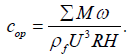 (3)
(3)
The blade lift coefficient cl and blade drag coefficient cd are defined as:
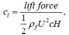 (4)
(4)
and
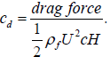 (5)
(5)
Where, c is the blade chord length.
The blade normal force coefficient cn and thrust force coefficient ct are defined as:
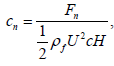 (6)
(6)
and
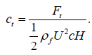 (7)
(7)
where Fn and Ft are the blade normal force and blade thrust force, respectively.
The Reynolds number for the vertical turbine is defined as:
 (8)
(8)
where υ is the kinematic viscosity of fluid flow.
As mentioned in Section 1, it has taken more than 2000 years for mankind to use VAT to generate power. In recent years, research on VAT has become much more popular since the energy extraction efficiency is still lower compared with HAT. Different research methods are used for the VAT study. The research method for VAT can be classified into three general categories, i.e., analytical method, numerical method and experimental test. The analytical solution is to use classic theories and methods to solve the forces acting on the VAT blade or the fluid field variables. Three different mathematical models are used in the scientific and industrial fields based on different theories such as the stream tube model based on the momentum theory, the vortex model based on the potential flow theory and the cascade model that uses Bernoulli’s equation. Numerical solution is to solve the governing equations of viscous/invicid fluid flow by using numerical methods for VAT studies. Experiential test is also widely used for the VAT research as a validation or confirmation of the analytical or numerical results. Detailed discussions and reviews of these methods are provided in the following paragraphs.
Analytical Solution
Stream tube model (momentum theory)
The stream tube method is based on the momentum theory (or the Newton second law). The forces acting on the turbine blade are equal to the rate of change of the momentum of the fluid flow. Based on this equation, the forces acting on the blade and the overall power coefficient could be solved by the momentum difference of the fluid flow between the upstream and downstream regions. Additional functions such as Bernoulli’s equation are needed [11,12].
The turbine blades are usually replaced by the actuator disk. A stream tube is selected which can cover the entire actuator disk. The cross-section area of the stream tube in the upstream region is smaller than the actuator disk, while the cross-section area of the stream tube in the downstream region is larger than the actuator disk. The following expressions could be derived based on the momentum theory:
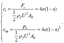 (9)
(9)
where Ad is the cross-section area of the stream tube in the downstream region, a is the coefficient of induced velocity, po is the power outputof the turbine. It is clear that the thrust coefficient of the turbine blade reaches its maximum value of 1.0 when a is 0.5. When a=1/3, the power coefficient cop reaches its maximum value of 16/17 (i.e., 0.593). This is the upper limit of the kinetic renewable turbine which is known as Betz limit.
There are three different categories for the stream tube method based on different treatments on the stream tube. They are the single stream tube method, the multiple stream tube method and the double multiple stream tube model. The single stream tube method is a method which contains only one stream tube to cover the entire actuator disk. The multiple stream tube method can divide the actuator disk into several isolated stream tubes and apply the momentum theory to each of them. This method can consider the influence of the blade position on the induced velocity. The double multiple stream tube model further divides the stream tubes of the multiple stream tube method into an upstream region and downstream region. The wake flow of the upstream region is the incoming flow of the downstream region in each stream tube. This method can consider the influence of the upstream blades on the downstream blades. Thus, higher accuracy could be achieved.
The stream tube method is widely used in the industrial field because of the simplicity of the mathematical formula and its good accuracy at low tip speed ratio and small solidity [8,10,13-19]. However, the accuracy will reduce when applying this method to a high solidity or high tip speed ratio condition. The calculation could be diverse if the tip speed ratio is very large [20]. This method cannot solve all the variables of the fluid field.
Templin [8] used the stream tube model to predict the power coefficient of the vertical axis turbine. In his study, the single stream tube model was used which applies one stream tube for the whole turbine actuator disk. The induced velocity was assumed to be constant throughout the actuator disk. The curved blade shape and the dynamic stall effect were taken into account. Different parameters such as cross section shape, solidity and the turbine height diameter ratio were studied.
Camporeale and Magi [18] compared the stream tube results with the experimental results of the vertical axis turbine model. The turbine blades were pitching about the pivotal axis through the Voith-Schneider system. A single actuator disk with the single stream tube method was used. Good agreement between stream tube results and the experiment results was achieved which provided the possibility of using the single stream tube method to predict the power coefficient and the energy extraction efficiency of a variable pitch vertical axis turbine system.
Vortex model (potential flow theory)
The vortex method is based on the potential flow theory to solve the unsteady fluid field with rotating turbine blades [10,21-25]. It begins with establishing the mathematical formulas of the unsteady potential flow method, and then solves these formulas based on Boundary Element Method (BEM). Sources and sinks are assigned to the blade surface. Discrete vortexes are arranged on the blade surface and the blade wake. The wake vortexes move with the fluid particles and ignore the influence from the dissipation, free-surface and wave. It assumes an incompressible fluid field and irrational field except for the blade surface and wake vortexes. All the discrete vortexes follow the vorticity conservation law. The vorticity magnitude is calculated by the Kutta condition. The forces acting on the turbine blade and the overall power coefficient could be solved with the correction for the viscous effect [11]. Compared with the stream tube method, the vortex method is able to calculate the blade vortex interaction, the blade pressure distribution, the unsteady effect and the instantaneous forces of the blade. However, the calculation time is much more than that for the stream tube method and it has a worse accuracy than the blade force calculation with a low tip speed ratio because of the large angle of attack of the blade and dynamic stall [20].
As early as 1978, Wilson [23] used this model to predict the performance of the Giromill straight blade vertical axis wind turbine. He found that the vertical axis turbine and the horizontal axis turbine have the same limit of the power coefficient and inline force coefficient. The cross wise force decreases with the groves of the tip speed ratio of the vertical axis turbine.
Wang et al. [26] designed a two dimensional vortex panel method to calculate the unsteady straight blade vertical axis turbine with variable blades. Their results showed good agreement with the experimental data. They also found that their two dimensional vortex panel method has better accuracy than the classic free vortex model and was simpler than the vortex method combined with finite element analysis.
Cascade model
Cascade is defined as the arrangement of turbine blades with equal distance. It is the fundamental physical phenomenon of the turbine machine. The cascade model is used to assume the turbine blades that are lying in a straight line. The interval between the blades in the cascade model is equal to the circumferential distance of them in the original configuration. Bernoulli’s equation is used to set up the mathematical relationship between the incoming flow velocity and the downstream velocity. Semiempirical expressions are necessary to determine the induced velocity through the downstream velocity.
The cascade model is workable for both high and low solidity and both large and small tip speed ratios of the vertical axis turbine. The instantaneous forces can also be solved by this model. Different effects such as turbine blade Re changes for different time instants, the aspect ratio effect and the flow curvature effect can be taken into account during the cascade model calculation [12].
Hirsch and Mandal [27] first used the cascade model for the calculation of the vertical axis wind turbine. Mandal and Burton [28] also applied this method to study the turbine dynamic stall effect for the vertical axis wind turbine.
Computational Fluid Dynamics (CFD) (Numerical Method)
The CFD method is used to calculate the entire fluid field by solving the partial differential fluid governing equations (Navier- Stokes equations for viscous flow or Euler equations for inviscid flow). Using the CFD method to solve the renewable energy turbine problem has become more and more popular in recent years [29-40]. The CFD method has many advantages, such as all of the information is available for the calculated fluid field. CFD can also simulate with a full scale model. Because of the characteristics of the vertical axis turbine, a mesh moving method, such as the sliding mesh technique, is necessary for the VAT simulation.
Hwang, et al. [29] simulated the straight blade vertical axis wind turbine using the CFD method. Both the cycloidal blade system and the individual active blade control system are considered in their study. Their results showed that the power output of the turbine with the cycloidal blade system is 30% higher than that with the classic fixed pitch blade. They also found an optimized blade pitch angle variation method for the vertical axis turbine with an individual active blade control system by maximizing the tangential force of the blade to reach the highest power output. They also studied the blade cross-section shape effect using the CFD method through the NACA 4-digit and NACA 6-series. A sensing and actuating system was also designed to achieve both the cycloidal blade system and the individual active blade control system.
Experiment
Experimental testing is one of the most traditional methods for studying the behaviour of renewable energy turbines. There are two general facilities for the VAT experimental test, i.e., the wind tunnel test and the towing tank test. The VAT experiments have two different test methods. One of them is to connect a motor to the VAT shaft and rotate the VAT at a certain angular speed of the motor during the test. This method is used to investigate the VAT in the stable working state only. The other method is to rotate the turbine by the fluid forces. Thus, the rotation speed of the turbine is not a fixed value during the experiment. This method could be used to study the stable working state of a VAT as well as its start-up and cut off ability.
Strickland, et al. [10] carried out a series of experiment on the vertical axis turbine and repeated the experiment result using the vortex model. The experiment was in a 1.25 m × 5 m × 10 m towing tank. The reason for using a towing tank instead of a wind tunnel to test the vertical axis wind turbine was because the water tank is able to visualize the streak line and the flow structure. They injected dye through the trailing edge of the turbine blade by using a pressurized dye injection system, so the vortexes and flow structure could be detected. Strain gages were used to measure the force of the turbine blade. They were located in the root of the turbine strut. Strain gage bridges were also used to make sure the strain gages were only sensitive to the indicated forces. They tested the straight blade vertical axis turbine with one blade, two blades and three blades, respectively. The turbine blade was in a cross section of NACA0012. The span of the turbine blade is 1.1 m and the chord of the blade is 0.0914 m. The diameter of the turbine is 1.22 m. Three tip speed ratios of the turbine were tested, i.e., 2.5, 5.0 and 7.5 with a fixed Reynold’s number of 4×10⁴. A good agreement was achieved between the analytical results (the vortex model) and the experimental results.
Klimas [41] compared the results from the theoretical conservation of the momentum-based aerodynamic model and the experimental tests for a vertical axis turbine. The turbine rotor radius is 8.5 m with a cross section of NACA0015. He discussed the blade-wake vortex interaction effect, the dynamic stall effect, the apparent mass effect and the circulatory effect of the vertical axis turbine by comparing the analytical and experimental results. He also found a large database for the turbine’s performance by using a symmetrical cross section. However, there was a lack of results and research on the performance analysis of the asymmetrical blade turbine at that time. A better agreement has been achieved for the dynamic model than for the Quasi-steady model compared with the experimental results based on his study.
Takamatsu, et al. [42] tested the vertical axis turbine performance on a narrow channel. An open channel with a depth of 1.2 m was used. An orifice-meter was used to measure the mass flow rate of the fluid flow. The shaft of the vertical turbine was connected to a flywheel through a torque sensor. The diameter of the vertical axis turbine rotor is 0.1 m. The chord length of the turbine blade was 0.03 m and the span of the blade was 0.3 m with a cross section of NACA0030. The best performance could be achieved when the double blade vertical axis turbine was located in the narrowest channel. They also predicated the results by using theoretical analysis. However, the theoretical results were not in good agreement with the experimental results of the instantaneous torque value and the peak energy extraction efficiency. These disagreements were because the circular motion effect and the unsteady effect of the fluid flow were ignored during the theoretical analysis.
Kiho, et al. [43] tested a straight blade vertical axis tidal turbine. Their experiments were tested at Kurushima straits in Ehime prefecture from 1983 to 1988. The turbine was designed as a three blade Darrieus type turbine. The blades have a cross section of NACA6330018, with a chord length of 0.3 m and a span of 1.6 m. The turbine radius is 0.8 m. A gear box and synchronous generator were designed for this turbine. Different parameters were measured and analysed for the power extraction through the vertical axis tidal turbine in extreme marine conditions. Their results showed that marine kinetic energy could be extracted when the incoming flow is larger than 1.0 m/s. They observed the highest energy extraction efficiency of 56% for their designed tidal turbine at the tip speed ratio of 2.1 (incoming flow of 1.1 m/s).
As discussed in Section 1, the energy extraction efficiency of VAT is lower than HAT. Since the 1970s, several parameter studies and performance enhancement methods for VAT have been investigated and invented. The most typical ones are listed in the following paragraphs.
Solidity of VAT
The most effective way to change VAT’s performance is to optimize the turbine or blade characteristics. The turbine or blade characteristics include the turbine blade profile, the blade numbers, the diameter of the turbine and the turbine blade chord length. A non-dimensionalized parameter solidity s σ is introduced to quantify the main geometrical characteristics of the Darrieus turbine:
 (10)
(10)
where N is the number of turbine blades.
Islam, et al. [44] tested different VAT blade cross-section profiles to improve the small capacity straight blade VAT in its starting and overall performance. Their results show that the classic NACA 4-digit systemic foils are unsuitable for small capacity straight blade VATs since their hydrodynamic performance is insufficiently high. They also suggested a high-lift and low-drag asymmetric foil with camber, high thickness, large leading edge radius and sharp trailing edge as the VAT blade cross section.
Islam et al. [45] tested different blade profiles by using several methods. The hydrodynamic performance of LS-0417 was found as the best among different foils under small Re and small λ but the cop was much smaller than that of the classic NACA0015 foil. A new type foil named MI-VAWT1 was designed by them which achieved a better performance under small Re and small λ and kept the same performance under medium Re.
Beri and Yao [19] tested the VAT performance by using a NACA2415 camber foil blade. Their results showed that the NACA2415 camber foil blade has a good start ability but lower energy extraction efficiency.
Castelli et al. [32] tested three different blade profiles, which are classic NACA0021, DU 06-w-200 and cambered NACA0021. Their results indicated the best performance was achieved by using the cambered NACA0021 and up to 4% enhancement of the energy extraction efficiency compared with the other two blade profiles. A performance improvement operation was observed in the downwind region of the cambered NACA0021 blade.
Castelli et al. [46] tested the solidity effect by changing the turbine blade numbers. It was found that using a larger σs results in the peak cop occuring at smaller λ, but the value of peak cop was reduced. A torque fluctuation and vibration reduction effect was observed by using larger Cop values. The normal force of the turbine blade was also observed to be reduced by using larger σs values.
Variable Pitch Effect for VAT
There are many factors which influence VAT energy conversion efficiency. From the flow point of view, dynamic stall is one of the phenomena which significantly reduce device efficiency. Stall occurs due to flow separation when a turbine blade rotates to a position at a large angle of attack. Once it appears, the blade lift force drops significantly leading to reduced overall energy extraction efficiency. This is very undesirable for the lift force driven VAT and always happens at small tip speed ratios (also known as the self-starting problem). The idea of variable pitch is to improve the self-starting performance of VAT. It is generally accepted that the variable pitch technique could enhance the turbine performance at small λ [47].
As early as the 1970s, Drees [48] and Grylls et al. [49] tested the VAT performance by using a variable pitch blade which was driven by a central cam. Grylls et al. [49] carried out experiments on four different pitch amplitudes. A good performance at small λ and better self-start ability were achieved under large blade pitching amplitude. However, the whole turbine system cannot accelerate to a larger λ. By reducing the blade pitching amplitude, better peak cop results could be achieved but the self-start ability of the turbine diminished.
Pawsey and Barratt [50] modelled the central cam variable pitch VAT by using the momentum theory. A range of pitch amplitudes from 0° to 30° were considered in their work. Corresponding power coefficients were predicted which confirmed the conclusion by Grylls et al. [49].
Schönborn and Chantzidakis [51] designed a cyclic pitch control turbine by using both the theoretical and experimental methods. Their results showed an enhancement in the turbine performance at small λ. The cyclic pitch control turbine can actively reduce the blade angle of attack to prevent the cavitation at large turbine rotational speed. By using the hydraulic actuation, the turbine can also have the emergency shutdown configuration.
Hwang et al. [52] carried out both numerical and experimental research on the cycloidal turbine. Their results show the turbine has the peak cop value at small λ when σs is large. A 25% enhancement of the energy extraction efficiency was also observed by using the individual blade control.
Kiwata et al. [53] designed a four-bar linkage variable pitch turbine. The pitch amplitude and offset angle are both able to change by using different lengths of the link. By using the four-bar linkage, VAT has the same start-up wind velocity but a higher rotational speed. The peak performance of the VAT energy extraction efficiency is also enhanced.
Jing et al. [54] experimentally tested three different variable pitch control turbines. These are cycloid type, spring-control type and passive variable pitch type turbines. Solidity, eccentric ratio, spring stiffness and other parameters were tested by their experiment. A positive correlation was found between cop and solidity as well as the eccentric ratio for the cycloid type turbine. A better hydrodynamic performance occurs when using a stronger spring for the spring-controlled turbine. For the passive pitch control turbine, a smaller pitch angle limit has a better energy extraction efficiency performance. Corresponding numerical analysis of the spring-controlled variable pitch VAT was also carried out by Sun et al. [55].
Pryor [56], Nemec [57], Stephens et al. [58], Stephens and Else [59] and Paluszek and Bhatta [60] also invented and patented different methods for the variable pitch vertical axis turbine.
Flow Directional and Augmentation Channel Effect for VAT
Another way to enhance the VAT performance is to use the flow directional and augmentation channel (or named duct). The idea of the flow direction and augmentation channel for VAT was first introduced by the diffuser augmented of horizontal axis wind turbines [20,61]. By using the channel to induce a sub-atmospheric pressure, the flow velocity around the turbine rotor could be increased and then improve the VAT performance [62,63].
Faure et al. [64] first applied a duct on a VAT under river to change the water current direction and speed. After testing, the interaction between the duct and turbine blade was observed which decreased the VAT performance.
Kirke [65] tested the energy extraction efficiency of vertical axis turbines with a duct device. A triple enhancement of the VAT efficiency was observed by using the duct devices. In addition, the VAT efficiency could exceed the Betz limit, which equals 0.593 and is the upper limit of the efficiency for a kinematic energy absorber as indicated in Section 3. They also pointed out the advantages of using duct devices, for example that they are environmentally friendly (especially for water animals), minimize turbine size and enhance rotor speed.
Roa et al. [66] tested two different channel devices, namely EPPLER-420 and NACA11414, for VAT by using experimental and numerical methods. It was observed that the flow was accelerated by using the channelling devices and the turbine blade generated more torque compared with a plain turbine. They could not determine the best configuration with their study and further investigations were suggested.
Gaden and Bibeau [67] tested a series of channeling devices by using a momentum source turbine model. A 3.1 times enhancement by using the channeling devices was observed compared with the plain turbine and an optimized dimension was also found for the channeling devices.
Castelli et al. [68] tested a “C” shape shroud device for the VAT and a 60% enhancement was observed when using it. The effect of a “C” shape shroud is to let the instantaneous torque of the turbine smoother when applies it onto the upstream of the VAT. While the amplitude of the instantaneous torque of the turbine could increase when applied to the downstream of the VAT.
Georgescu et al. [69] tested the “S” shape duct devices by using the numerical method. A VAT performance enhancement effect was observed by using this device. A half “S” shape duct device was also suggested to achieve a better performance.
Other Parameter Studies of VAT
Some other parameter studies of VAT are listed below.
Plasma actuators
A research group at the Israel Institute of Technology came up with an idea to control the dynamic stall for the vertical axis wind turbine by using plasma actuators. Greenblatt et al. [70] carried out experiments on large σs small scale VAT by applying dielectric barrier discharge (DBD) actuators on the leading edge of the turbine blade. A series of parameters were studied and a 38% enhancement was observed by using the DBD actuators. Ben-Harav and Greenblatt [71] used a pulsed DBD actuator to control the dynamic stall on a VAT. Based on their experimental results, they found that the VAT performance was enhanced during the whole working region by using this device and the dynamic stall was also prevented/controlled. Greenblatt et al. [72] analysed the vortex field of the DBD controlled VAT by using the PIV technology. Their results showed that by using the DBD actuators, the dynamic stall vortexes became small and were close to the blade’s surface so the dynamic stall effect could be reduced.
Trailing edge (flap) control
Beri and Yao [19] studied the VAT performance with the trailing edge modified blade. A positive cop was observed in their study with this type of blade. Sneeringer [73], Paluszek and Bhatta [60] and Haar [74] all invented and patented the VAT design by using a rotatable trailing edge blade. The top view of a rotor assembly illustrating the adjustments of blade ailerons relative to a prevailing wind with the variable flap method by Haar [74]. Thus the lift force of the turbine blade could be increased and the total performance of the turbine could be enhanced. Haar [74] also used a blade extension element to achieve the turbine rotational speed control. Xiao et al. [38] tested active oscillation trailing edge flap effect for VAT. Positive results on the energy absorb ability was observed.
Turbine blade elasticity
In order to achieve a large energy output, the size of offshore turbines are getting larger and larger, especially for HAT [75,76]. As a large scale HAT, the blade usually suffered from high unsteady loads generated by turbulent wind and large gravtational forces. These unsteady loads lead to the blade deformation and even can break the blade. Several researches aimed to reduce the loads on the blade by using composite materials, such as “Morphing Blade” (MB) [77-79]. Because of the exist of the radial centrifugal force of a VAT blade, the unsteady loads and blade stress of a VAT are much more remarkable than a HAT. However, relevant research on VAT blade stress prediction and elimination is still limited. This might because of the nature of the VAT blade operation condition (cyclic rotational motion) that generates larger variation of unsteady loads compared with HAT. Hameed and Afaq [80] tested the VAT blade stress distribution and the bending deformation with different thickness under extreme fluid load condition. Butbul et al. [81] tested the chordwise flexible VAT blade by using MB through experiment and Finiet Element Method (FEM). They observed positive effect at low tip speed ratio region, but harmful effect at large tip speed ratio region in terms of the energy extraction efficiency. Liu and Xiao [82] simulated the blade stress distribution and deformation for a three-dimensional VAT by using different materials (Young’s Modulus effect) through fully coupled CFD and Fluid Structure Interaction (FSI) method. Their results show that the peak energy extraction efficiency could be enhanced by using medium flexible material compared with the rigid one. However, the energy extraction efficiency drops significantly with large flexibility material of the VAT blade.
In this paper, relevant literatures on the research methods of straight blade vertical axis turbine and different parameter studies aimed for enhance the energy extraction performance of vertical axis turbine have been reviewed. The following conclusions and gaps could be identified:
• Three general research methods are used to predict or design a VAT, which are analytical method, numerical method and experimental test. Different methods has its own strength and weakness which are suitable for different purposes. A comprehensive database for aero-/hydro-dynamic performance of different VAT is needed.
• There are a lot of parameters of VAT which can influence its energy extraction efficiency. Most of the past researches are focusing on the design of rigid blade pitch motion, design of additional equipment (such as channel or duct), etc.
• Some of the researchers patented vertical axis turbine blade with flap, but there is a lack on the systematic research of the effect of the flap as well as under active or passive motion.
• Despite the advantages of new material, such as MB, and research on its application for HAT, the investigation of the potential application of bio-inspired composite material on to VAT is limited. This is partially due to the even larger variation of unsteady loads applying on a VAT blade during its cyclic rotational motion as compared to a HAT.
It is believed that this review paper provides a reference and general guidelines for the industrial design of the straight blade VAT.
The present article is a part of the author’s PhD thesis. The author’s PhD research was supervised by Dr. Qing Xiao and Prof. Atilla Incecik. The author obtained his PhD degree from the department of Naval Architecture, Ocean and Marine Engineering, University of Strathclyde, Glasgow, UK.