ISSN ONLINE(2278-8875) PRINT (2320-3765)
ISSN ONLINE(2278-8875) PRINT (2320-3765)
Elizabeth Sebastian1,George Joseph2, Dhanesh R3, Cyril Baby4, Cherian Mathew5
|
| Related article at Pubmed, Scholar Google |
Visit for more related articles at International Journal of Advanced Research in Electrical, Electronics and Instrumentation Engineering
This paper is about creating a reliable system that takes over the task of identifying free slots in a parking area and keeping the record of vehicles parked very accurately. This project lessens the human effort at the parking area to great extent such as in case of searching of free slot by the driver and calculating payment for each vehicle using the parking area. This system employs ATmega 32A as its heart which comes under AVR family of microcontrollers. The various steps involved in this operation are vehicle identification, free slot detection and payment calculation. Vehicle identification is carried out using RF transceivers and here it is suggested that each vehicle to have unique identity. Free slot detection is carried out using IR transceivers and at the instance of vehicles leaving the parking area. Payment calculation is done on the basis of period of parking and this is done with the help of real time clock (RTC). For the system to be more reliable, RTC is powered from a separate dc source.
Keywords |
| ATmega32A, Slot Detection, IR Transceiver, Vehicle Identification, RF Transceiver, Real Time Clock (RTC) |
INTRODUCTION |
| Parking is a major problem the cities in India face currently. The problem rises due to the lack of space for the parking facility. The solution by providing more space is not practical. The only solution is to efficiently use the available space and this can be done by dividing the space into different slots rather than parking the vehicles randomly. The only problem that may arise is to know whether the slots are fully occupied or which slot is vacant. Moreover there is a lot of manual labour involved for this process for which there is lot of investment required. Our project aims at finding a solution to this by creating a miniature of the parking system and checking for the availability of vacant space in the system with the help of IR transmitting and receiving devices. We also provide an additional feature giving individual ID’s for each car so that only the registered cars are allowed to park in the system accomplished with the aid of RF transmitter and receiver. |
INTERFACING OF RF MODULE |
| The RF module, as the name suggests, operates at Radio Frequency. The corresponding frequency range varies between 30 kHz & 300 GHz. Figure 1 shows a typical RF transceiver module. In this RF system, the digital data is represented as variations in the amplitude of carrier wave. This kind of modulation is known as Amplitude Shift Keying (ASK). |
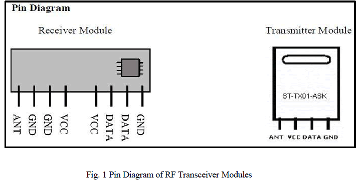 |
| Transmission through RF is better than IR (infrared) because of many reasons. Firstly, signals through RF can travel through larger distances making it suitable for long range applications. Also, while IR mostly operates in line-of-sight mode, RF signals can travel even when there is an obstruction between transmitter & receiver. Next, RF transmission is more strong and reliable than IR transmission. RF communication uses a specific frequency unlike IR signals which are affected by other IR emitting sources. This RF module comprises of an RF Transmitter and an RF Receiver. The transmitter/receiver (Tx/Rx) pair operates at a frequency of 434 MHz. An RF transmitter receives serial data and transmits it wirelessly through RF through its antenna. However, RF transceiver modules are costlier than IR transceiver modules. |
| The RF module, as the name suggests, operates at Radio Frequency. The corresponding frequency range varies between 30 kHz & 300 GHz. Figure 4 shows a typical RF transceiver module. In this RF system, the digital data is represented as variations in the amplitude of carrier wave. This kind of modulation is known as Amplitude Shift Keying (ASK). Transmission through RF is better than IR (infrared) because of many reasons. Firstly, signals through RF can travel through larger distances making it suitable for long range applications. Also, while IR mostly operates in line-ofsight mode, RF signals can travel even when there is an obstruction between transmitter & receiver. Next, RF transmission is more strong and reliable than IR transmission. RF communication uses a specific frequency unlike IR signals which are affected by other IR emitting sources. This RF module comprises of an RF Transmitter and an RF Receiver. The transmitter/receiver (Tx/Rx) pair operates at |
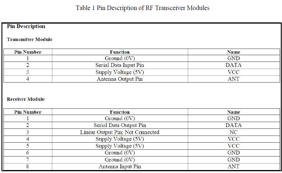 |
| a frequency of 434 MHz. An RF transmitter receives serial data and transmits it wirelessly through RF through its antenna connected at pin4. The transmission occurs at the rate of 1Kbps - 10Kbps.The transmitted data is received by an RF receiver operating at the same frequency as that of the transmitter. Table 1 shows the associated pin description of RF transmitter and receiver chips. |
BLOCK DIAGRAM |
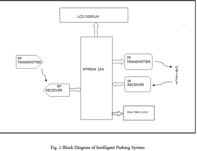
| The outline of intelligent parking system is shown in Figure 2. This system consists four parts: RF Communication, IR Detection, RTC interfacing and LCD display. |
 |
WORKING |
| This project develops a prototype of parking slot tracking and managing system. The system can act as a way finder to guide car drivers inside the car park to show whether there is an empty parking slot available inside the car park and guide drivers to the location of these available parking slot. This project consists of three parts, which are vehicle identification using RF transceiver, parking slot detection using IR sensor and wage calculation. The various techniques involved and their working is described below. |
A. Vehicle Identification |
| The first step of the project is to identify the vehicle. This process involves the use of RF transceivers. The identification is a must while coming to calculating the payment. The vehicle to be entered is asked to send its identity through RF transmitter. For this purpose all the vehicles using the parking slot must have unique identity. The microcontroller in the parking system then recognizes the vehicle on receiving the identity sent over radio waves with the help of a RF receiver. Moreover, the identification process is carried out at the time of leaving. The duration of parking of that particular vehicle is noted for payment calculation. |
B. Free Slot Detection |
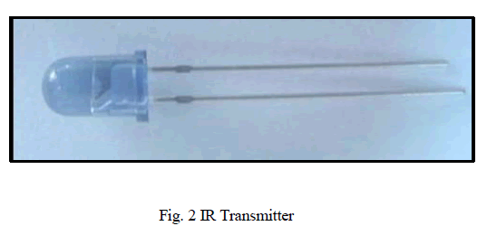
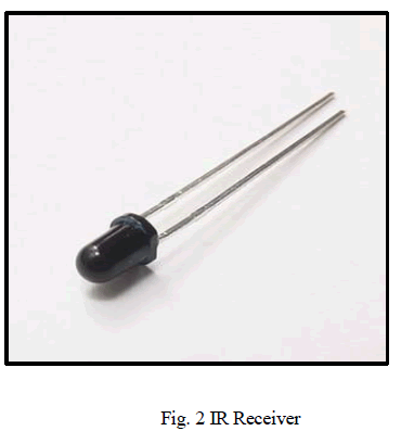
| The next job of the controller is to find a free parking slot for the entered vehicle. This is realized using IR transceivers. The transceiver pair is kept face to face in each slot. If the slot is filled with vehicle the receiver won’t receive any IR rays emitted by the transmitter. So as explained the voltage drop across transmitter varies. This voltage is given an analog input to ADC in the microcontroller.Atmega32 has an inbuilt ADC which can work on both 8bit or 10bit precision. ADC converts the analog signal to digital equivalent and is interpreted by the controller. |
 |
 |
C. Payment Calculation |
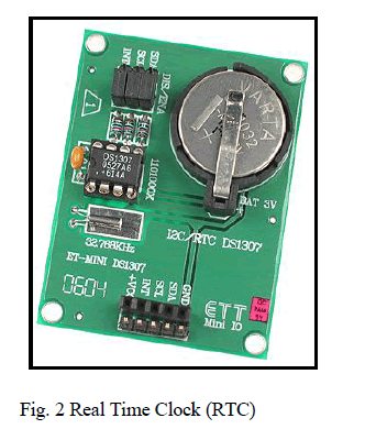
| Another advantage of the system is that it automatically calculates the payment as the vehicle leaves the parking slot. The calculations are done based on the time spent by each vehicle in the parking slot. This is implemented by interfacing real time clock (RTC) module to the microcontroller. RTC keeps record of real time accurately. So as each vehicle enters the lot the time is retrieved from RTC and is saved in the database. This process is again done while the vehicle leaves. Taking the difference gives the exact time the vehicle has used the parking slot. |
 |
CONCLUSION |
| The circuit of our project was designed and implemented. The prototype is simulated by sending id through RF module and free slots were displayed in LCD. The Intelligent Parking System checked for the availability of vacant spaces in the parking area and displayed the slot that is available for parking to the vehicle that just arrived at the entrance. This project is a useful tool for ensuring proper parking system and reduces the tedious job of finding the free slots available at the parking area. |
ACKNOWLEDGMENT |
| We hereby express our sincere gratitude to the Head of the Department of Electrical And Electronics Engineering, Prof. K. Radhakrishnan for providing us with the necessary arrangement for the completion of our project. We also thank our faculty advisor Prof. Bindu Elias for her valuable guidance. We express our sincere gratitude to our guide Asst. Prof. Jeena Joy, Department of Electrical And Electronics Engineering, without whose valuable guidance and support the project would not have been a success. We thank her for the good will and encouragement extended to us. Our heartfelt gratitude to Asst. Prof. Eldhose K.A. and Assoc. Prof. Sini Paul, Department of Electrical & Electronics Engineering, for their constant support and guidance. |
References |
|