International Journal of Advanced Research in Electrical, Electronics and Instrumentation Engineering
ISSN ONLINE(2278-8875) PRINT (2320-3765)
ISSN ONLINE(2278-8875) PRINT (2320-3765)
P. Deepakumari1, Dr. P. Arockia Jansi Rani2
|
| Related article at Pubmed, Scholar Google |
Visit for more related articles at International Journal of Advanced Research in Electrical, Electronics and Instrumentation Engineering
This paper describes the analysis and design of a low cost sensorless three phase inverter brushless dc motor drive. The absence of hall sensors give rise to a sensorless control therefore the commutations are obtained by the zero crossing detectors. The proposed system employs Butterworth low pass filters (LPF) to prevent multiple output transitions from noise or ripple in terminal voltages. The performance of the proposed work is compared with that using Chebyshev LPF. The simulation results give the performance of developed sensorless technique.
Keywords |
| Brushless dc (BLDC) motor, MOSFET/IGBT, Butterworth LPF, Chebyshev LPF sensorless control, simulation models. |
INTRODUCTION |
| Brushless Direct Current (BLDC) motors are one of the motor types which currently becoming popular. BLDC motors are utilized in wide range of industries such as consumer electronics, medical, automotive, industrial automation equipment and aerospace. The commutation of BLDC motors are not the same as the brush type DC motor. The mechanical commutator of the brush dc motor is replaced by electronic switches, which supply current to the motor windings as a function of the rotor position. This kind of ac motor is called a brushless dc motor, since its performance is similar to the traditional dc motor with commutators. BLDC motors have many advantages compared to brush type DC motors and induction motors, listed as follows [1-5]: Better speed versus torque characteristics, High dynamic response, High efficiency, Long operating life, Noiseless operation, Higher speed ranges. |
| In addition, the ratio of torque delivered to the size of the motor is higher, making it useful in applications where space and weight are critical factors. Over the years of advanced technology development in power semiconductors, embedded systems, adjustable speed drives (ASDs) control schemes and permanent-magnet brushless electric motor production have contributed for reliable and cost-effective solution for adjustable speed applications. Household appliances are expected to be one of fastest growing end product market for electronic motor drives (EMDs) over the following next few years [19]. The major appliances include clothes washers, room air-conditioners, refrigerators, vacuum cleaners, freezers, etc. The automotive industry will also see the explosive growth ahead for BLDC type electronically controlled motor system owing to the compact design and high efficiency of BLDC motor. The appliances and devices use the electric motors to convert electrical energy into useful mechanical energy required by the load. Consumers now demand for lower energy costs, better performance, reduced acoustic noise, and more convenience features. In recent years, proposals have been made for new higher energy-efficiency standards for appliance industry, which will be legalized in near future [20]. These energy standards proposals present new challenges for appliance designers. |
| The 3-phase BLDC motors are well adoptable for industrial applications that require medium and very high speeds. Two important characteristics, low inertia and high peak torque, result in the motor capable of quick accelerations and decelerations. Sensor and sensorless control are two methods of control of BLDC motors [1-5]. In sensor control Hall sensors are normally used which need maintenance. An approach to position sensorless BLDC motor drive, a new algorithm for sensorless operation [7] and sensorless control without signal injection [8] are reported. Two types of sensorless control techniques of PM BLDC motors are discussed [12]. The first type is the position sensing using back EMF of the motor, and the second one is position estimation using motor parameters. |
| The position estimation scheme usually needs complicated computation, and the cost of the system is relatively high. The back EMF sensing scheme is the most commonly used method, which is adopted in this paper. |
| `In a 3-phase BLDC motor, only two out of three phases are excited at any time, leaving the third phase winding floating. The back EMF voltage in the floating winding can be measured to establish a switching sequence for commutation of power devices in the 3-phase inverter.The conventional method of sensing back EMF is to build a virtual neutral point that will, in theory, be at the same potential as the centre of a Y wound motor and then to sense the difference between the virtual neutral and the voltage at the floating terminal. However, when using a chopping drive, the neutral is not a standstill point. The neutral potential jumps from zero up to near dc bus voltage, creating a large common mode voltage since the neutral is the reference point [9]. Meanwhile, the PWM signal is superimposed on the neutral voltage as well, inducing a large amount of electrical noise on the sensed signal. Proper sensing of the back EMF requires a lot of attenuation and filtering. The attenuation is required to bring the signal down to the allowable common mode range of the sensing circuit, and the low pass filtering is to smooth the high switching frequency noise. The result is a poor signal to noise ratio of a very small signal, especially at start-up where it is needed most. Consequently, this method tends to have a narrow speed range and poor start upcharacteristics. |
| To reduce the switching noise, the back EMF integration [13-22], third harmonic voltage integration [10] and flux estimation [7] were introduced. The integration approach has the advantage of reduced switching noise sensitivity. However, it still has the problem of high common mode voltage in the neutral. The flux estimation method has estimation error at low speeds. The torque ripples [11], current ripple, voltage drop, speed limitation [6], additional compensation circuit [14], not applicable for low load, poor reliability [17, 21&22], high frequency ripple, multiple output transitions, phase delay [18]. An indirect sensing of zero crossing of phase back EMF by detecting conducting state of free-wheeling diodes in the unexcited phase was also approached [6]. The implementation of this method is complicated and costly, while its low speed operation is still a problem. In this thesis a back EMF detection method, which does not require the motor neutral voltage is implemented. The back EMF can be detected directly from the terminal voltage by properly choosing the PWM and sensing strategy. The resulting feedback signal is not attenuated, providing a signal with a very good signal/noise ratio. |
SYSTEM MODEL |
| Theproposed system overcomes the aforementioned drawbacks and it uses the sensorless techniques based on a line to line voltage difference and a 120 degree start-up method with a high starting torque is suggested. The line to line voltage difference is used to compensate for the phase delay of the back-EMFs and the Butterworth low-pass filter (LPF) which can be used to prevent the multiple output transitions from noise or ripple in the terminal voltages.Here the dc voltage source is applied to the three phase inverter; Inverter output is connected to the BLDC motor. Output of the phase voltageis given to three phase BLDC motor and after sensing the three-phase terminal voltages; each of the three-phase terminal voltages is fed into an LPF to suppress the high switching frequency ripple or noise.The performance of the proposed work is compared with that using Chebyshev LPF so that which one is the best for the design of sensorless BLDC motor is analysed in this paper through MATLAB Simulink models. |
ANALYSIS OF BLDC MOTOR |
| Fig. 1 shows the equivalent circuit of a three-phase BLDC motor [23]. The typical mathematical model of the BLDC motor is described as: |
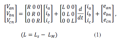 |
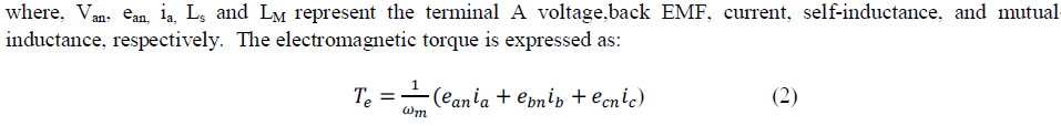 |
| where, wm is the rotor speed. Fig. 2 shows trapezoidal back EMF, current profiles, and Hall sensor signals of the three phase BLDC motor drive. |
 |
| The current pulse generation is a “120° on and 60° off” type. To drive the motor with maximum and constant torque/ampere, it is desired that theline current pulses be synchronized with the line-neutral back EMF voltages of the particular phase |
 |
SIMULATION RESULTS |
| In this section, the validity of the proposed sensorless technique is proved via some simulations. Fig. 3 shows the overall block diagram of the three phase inverter using IGBT/MOSFET BLDC motor drive in MATLAB Simulink. In these blocks the PI controller is used to regulate the speed of the motor by setting its proportional and integral gain. The output of this controller is given to the voltage source which is the input of the three phase inverter here the six step inverter which consists of three half-bridges, where mutually phase shifted by angle to generate three phase voltages using the hall signals from the line-line voltage difference block then these six gating pulses are used to operate the motor without the hall sensor so this is called as sensorless BLDC motor. |
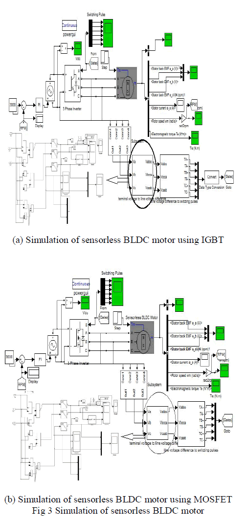 |
| Simulation is carried out at different speed references in the range of 200 rpm up to 3000 rpm. The proposed system uses Butterworth LPF in the terminal voltage to line voltage subsystem to produce the voltage pulses as the input of other subsystem to produce the switching pulses for the three phase inverter. The subsystem where the LPF is used is shown in fig. 3(b). The waveforms produced by the Chebyshev filter have ripples in pass band and stop band is shown in fig. 4. |
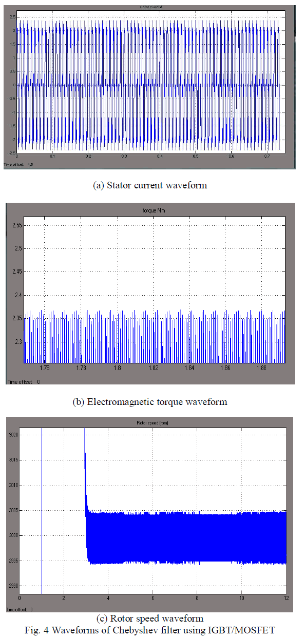 |
| Simulation of the subsystem using the Butterworth low pass filter give better phase linearity than that of Chebyshev filters in fig. 5. From this it shall be inferred that the design of sensorless BLDC motor drive using Butterworth LPF is better than that of using Chebyshev LPF. In the low power applications MOSFET is better than IGBT because of its switching speed and dynamic performance. |
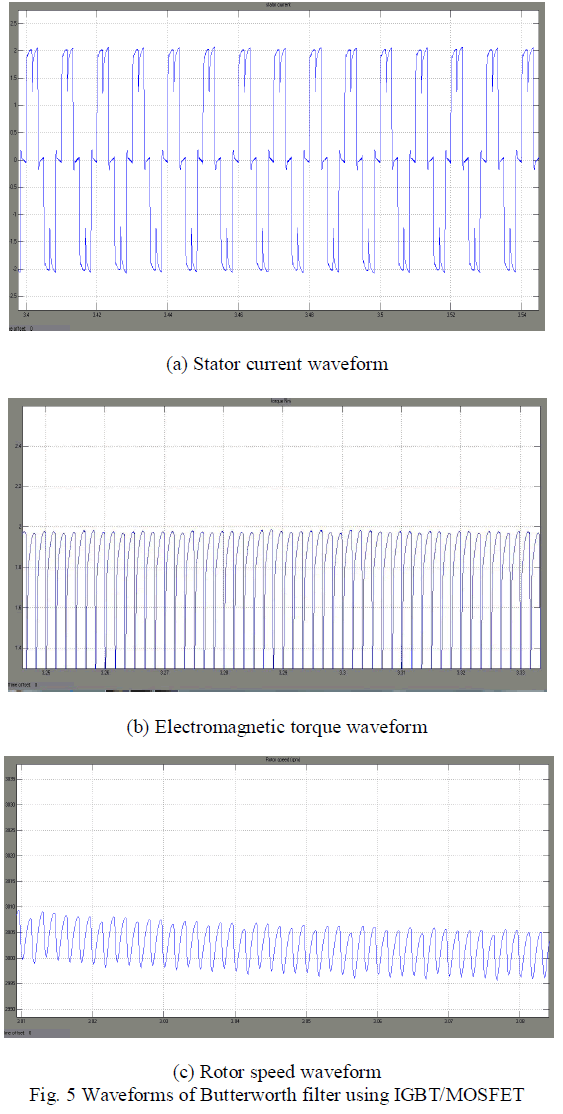 |
| Hence the Butterworth filter is better than the Chebyshev filter in phase linearity, group delay, waveform distortion, magnitude response and transition bandwidth has been verified by the simulation results of Sensorless BLDC motor drive. |
PERFORMANCE ANALYSIS |
| In this section the simulation of three phase sensorless BLDC motor is carried out at different speed references in range 200 rpm to 3000 rpm. When it reaches the 3000 rpm the performance of Butterworth and Chebyshev low pass filter using IGBT/MOSFET in a three phase inverter is shown in the table 1. The PI controller takes larger gain value for IGBT when compared to MOSFET in a three phase inverter. |
TABLE 1 |
| PERFORMANCE OF BUTTERWORTH & CHEBYSHEV LPF USING IGBT/MOSFET IN SENSORLESS BLDC MOTOR |
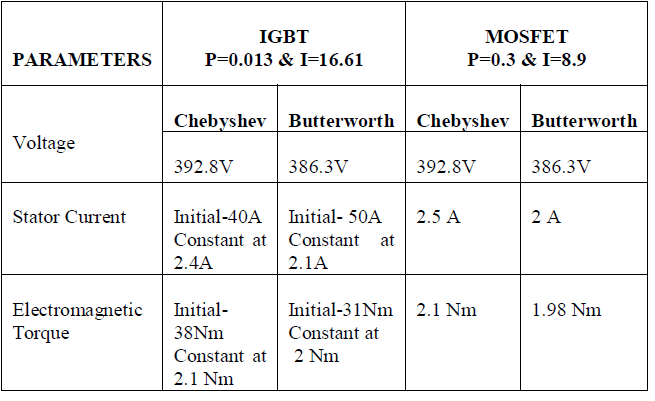 |
| The switching frequency of IGBT is smaller than the MOSFET switching frequency so there is a fluctuations in the stator current and electromagnetic torque therefore we chose MOSFET for the design of three phase inverter in low power applications. In the low pass filters Butterworth filter is selected for the design because its transition band is more when compared to Chebyshev filter which exhibits ripples in pass band and stop band and the Butterworth LPF require less number of components to construct the filter in hardware. |
CONCLUSION |
| This paper presents a sensorless control based on a line-line voltage difference of BLDC motor drive with a high starting torque and a potential start-up method with a terminal voltage. Here the phase lag of back EMF is reduced by line-line voltage difference and the output transitions are controlled by the low pass filter. The magnitude of the stator current is aligned by the rotor position which can be easily controlled by modulating the pulse width of specific switching devices in the three phase inverter. From the performance analysis, design a sensorless control of BLDC motor using IGBT/MOSFET and Butterworth filter is well suited for thehigh/low power applications as well as the automotive applications. Finally the proposed scheme has been successfully verified by simulation results. |
References |
|