ISSN ONLINE(2278-8875) PRINT (2320-3765)
ISSN ONLINE(2278-8875) PRINT (2320-3765)
Y.Jhansirani 1, S.Mallikarjunaiah 2
|
| Related article at Pubmed, Scholar Google |
Visit for more related articles at International Journal of Advanced Research in Electrical, Electronics and Instrumentation Engineering
The process of generation of electrical energy by the concept of power management with the presence of solar photovoltaic systems. Several new soft –switching technologies has been introduced. Taking into consideration as to improve energy capture resonant switched capacitor converters has taken, for voltage balancing modules. These are configured in parallel with strings of PV cells. The voltage balancing circuit transfers electrical charge between capacitor modules with soft switching operation reduction of power loss and EMI. These are configured in sub module level to improve energy capture even in the presence of shading or any mismatch occurs. This performs parallel ladder architecture that allows converter to handle only mismatch power and turn off if there is no mismatch that leads to optimize the maximum power from the PV system with higher conversion efficiency for a short circuit current mismatch gradient up to 40%.Since the circuit eliminates large magnetic components ,space requirement is less that is vertical foot-print less than 6mm and cost is low, reliability is high, insertion losses are less, and so complexity is less in the array.
Keywords |
| Solar photo voltaic cell, power management ,resonant converter. |
INTRODUCTION |
| Generation of electrical energy is basically depends upon the power management either by renewable energy resources as well as non- renewable energy resources. So, prominence of electrical energy generation by renewable energy resources is increasing a lot. Power management is nothing but increasing utilization of energy capture by reducing costs and solving hazards that occur in plant while in some operational and integration issues. In order to overcome the hazards the technology associated in efficient conversion and control of electrical power by power semi converter semiconductor devices have to be introduced when ever require in the plant that these devises are low cost and efficiency in high. The PV cells can be arranged in either series or in parallel combination A parallel combination is less sensitive voltage mismatch creates a bigger problem. So, preference of series combination of PV cells had taken to boost the output voltage. The traditional PV power management architecture is based on central inverter which implements MPPT algorithm to optimize the power flow. MPPT is a technique which is required to get maximum power flow from a solar array irrespective of the plant complexity and environmental conditions. The mismatch among PV panels may arise several problems. This mismatch will be due to direct shading, dust, debris, cell aging, and factory mismatch. To avoid the hotspot heating by pass diodes are placed in parallel with each PV cell one by pass diode for one PV cell. These diodes allows current to pass around shaded cells and there by reducing the voltage losses through the module. Reduce the amount of local heating at the shaded area. Throw away energy produced by these cells can in occur extra losses in the diodes that may cause several problems. These all will cause complicating the MPPT algorithm and potentially destabilizing the MPPT algorithm for central inverter. Thus make an effort of introducing decentralize power management for PV system. The first generation distributed power management is shown in figure (1). In figure 1(a) DC power is received by the power bus through DC-DC converters from PV panels. And from the power bus it is given to the on-grid inverter where the dc power is inverted to AC power and is given to the grid. Where as in the figure 1(b) the power from solar panels is given to the inverter and from inverter the power is given to grid through power bus . Each converter optimizes a single solar module with a MPPT algorithm |
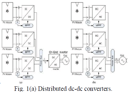 |
| Fig. 1(b) Distributed ac-dc micro inverters. |
| However ever by this approach, cost is high for DC-DC converters and also lower peak power production due to the poor conversion efficiency of converters, insertion losses. If the nominal PV array has some rating, the difference between output that obtained to the nominal rating of a PV array is defined as “insertion losses”. It requires a central inverter to operate the PV array with exact voltage such that unity conversion ratio is achieved. This may be complicated especially if there is shading in the array .So, an alternative architecture for PV energy optimization has been introduced. |
PROPOSED SYSTEM |
| As the growth of distributed power management architecture has increased the demand for dc-dc conversion, as a result number of dc-dc converters became available. This paper presents a switched capacitor converter topology that performs a higher efficiency even with a mismatch gradient up to 40%. The resonant switched capacitor converters are configured in parallel with the strings o f PV cells at theplace where bypass diodes are placed in traditional PV power management architecture and it is in figure(2).conversion, as a result number of dc-dc converters became available. This paper presents a switched capacitor converter topology that performs a higher efficiency even with a mismatch gradient up to 40%. The resonant switched capacitor converters are configured in parallel with the strings o f PV cells at the place where bypass diodes are placed in traditional PV power management architecture and it is in figure(2). |
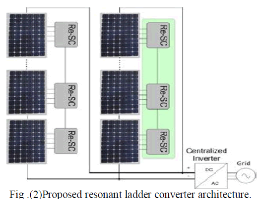 |
| The regulation objective of the proposed system is to enforce voltage ratios among series connected strings of PV modules. The voltage ratios of adjacent strings of cells are 1:1 in typical PV modules. Same number of cells are placed in each string and same technology have to be used in typical PV modules. |
| The converters are configured at the sub-module level to PV module that enables recovery of mismatch loss at the string of cell inside each individual panel. By this approach higher conversion efficiency is achieved. Also the proposed system implements other control and distributed functions. Central inverters are provided to recover any mismatch occur in the solar array. Thus the proposed system is used as an attractive alternative in large –scale installations ,since the cost is less as compare to that of traditional power management architecture. |
PERFORMANCE CHARACTERISTICS OF PROPOSED SYSTEM |
| The performance characteristics of resonant switched capacitor converters are shown in the figure(3).Normalized short circuit current (Isc) versus maximum power voltage (Vmpp) and maximum power current (Impp). Impp is linear with Isc to the first order .Vmpp stays within a narrow range for nearly a decade of variation of Isc.Since Vmpp is logarithmic with first order .Due to series and shunt resistive effects it has some higher order curvature. But in our proposed system this effects may be negligible even if maximum power voltage (Vmpp) depends on thermal gradient which cause deviation from 1:1 ratio. |
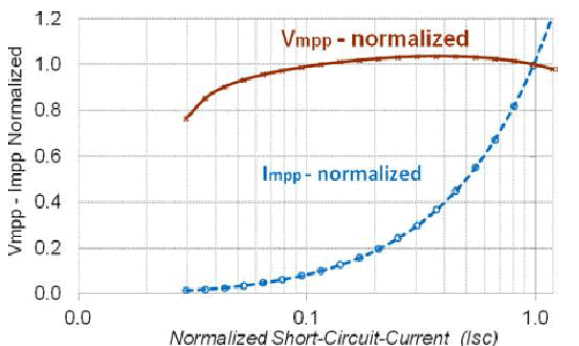 |
| Fig.(3) Comparison of maximum power current and voltage(Impp and Vmpp) versus short circuit current. |
| In example , there are Np panels and Ns strings of cells in a proposed system. Central inverter finds maximum power voltage for the array Vmp-Array. Each string of cells should operate at voltage Vstring=Vmp-Array/Np.Ns .Hence by the proposed system the strings of cells achieve maximum power voltage even though the effect of thermal gradient is up to 10-20% |
SOLAR POWER MANAGEMENT |
| The prominence of solar power management is increasing a lot, as global warming and energy policies have become a hot topic on the international agenda in last years. Developed countries are trying to reduce their green house gas emissions. Increasing the efficiency in PV plant, so the power generated increases is a key aspect. The efficiency of a PV plant is affected mainly by three factors. |
| (1).The efficiency of PV panel. |
| (2). Maximum power point tracking algorithm (MPPT). |
| (3). Efficiency of converter. |
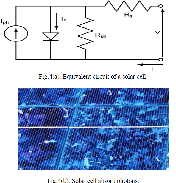
| Solar cells are basic components of PV panels. PV system use solar panels to convert sunlight into electricity. A small PV system may provide energy to a single consumer. Large grid-connected PV systems can provide the energy needed by many customers. A solar cell is an electrical device that converts the energy of light directly into electricity by the photovoltaic effect. It is a form of photoelectric cell which, when exposed to light, can generate and support an electric current without being attached to any external voltage source. The solar cell equivalent circuit are shown in figure 4(a).. |
| The operation of a photovoltaic (PV) cell requires 3 basic attributes: |
| (1) The absorption of light, generating either electron-hole pairs or exactions. |
| (2) The separation of charge carriers of opposite types |
| (3) The separate extraction of those carriers to an external circuit. |
WORKING PRINCIPLE OF SOLAR CELL: |
 |
| When explaining the working principle of photovoltaic cells we first need to know that sunlight is made out of tiny energy pockets called photons and the is shown in figure4(b). The bigger amount of the available sunlight the greater the flow of electrons and the more electricity gets produced in the plant. Photovoltaic cells are usually made of expensive materials such as silicon and also with fossil fuels. The electricity generated by photovoltaic panels is direct current. This means that there is a need for installing inverter. The amount of sunlight at your location plays key role in determining the economics of your solar power installation. Some areas receive more sunlight than other, and in these areas installing solar panels is more economically viable. |
MAXIMUM POWER POINT TRACKING |
| Solar cells have a complex relationship between solar irradiation, temperature and total resistance that produces a nonlinear output efficiency which can be analyzed based on the I-V curve. It is the purpose of the MPPT system to sample the output of the cells and apply the proper resistance (load) to obtain maximum power for any given environmental condition |
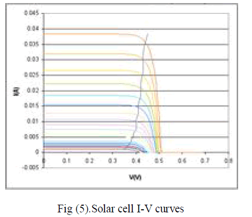 |
| The Solar Cell I-V Curve in Varying Sunlight is show above Figure (5). where a line intersects the knee of the curves where the maximum power point is located. Photovoltaic cells have a complex relationship between their operating environment and the maximum power they can produce. The fill factor, abbreviated FF, is a parameter which characterizes the non-linear electrical behavior of the solar cell. Fill factor is defined as the ratio of the maximum power from the solar cell to the product of Open Circuit Voltage Voc and Short-Circuit Current Isc. In tabulated data it is often used to estimate the maximum power that a cell can provide with an optimal load under given conditions, P=FF*Voc*Isc. For most purposes, FF, Voc, and Isc are enough information to give a useful approximate model of the electrical behavior of a photovoltaic cell under typical conditions. |
RESONANT CONVERTERS |
| Switched capacitor converters have been used to realize small size and light weight DC-DC converters in many kinds of electronic devices .However, conventional switched capacitor converters have an inherent drawback that their efficiency is much decreased as the output current is increases. So that their efficiency cannot be increased by decreasing their internal resistance. They may be limited to small output currents. |
| Increasing the frequency of operation of power converters is desirable, as it allows the size of circuit magnetic and capacitors to be reduced, leading to cheaper and more compact circuits. However, increasing the frequency of operation also increases switching losses and hence reduces system efficiency. One solution to this problem is to replace the "chopper" switch of a standard SMPS topology (Buck, Boost etc.) with a "resonant" switch, which uses the resonances of circuit capacitances and inductances to shape the waveform of either the current or the voltage across the switching element, such that when switching takes place, there is no current through or voltage across it, and hence no power dissipation. A circuit employing this technique is known as a resonant converter. |
| The major advantage of resonant switched capacitor converter over to switched capacitor converter is resonant cell will achieve nearly the same Reff-min (Minimum effective resistance) that switched capacitor cell obtained, but at lower frequencies. The distributed converter circuit architecture is shown in the figure (6). |
EXPERIMENTAL RESULTS |
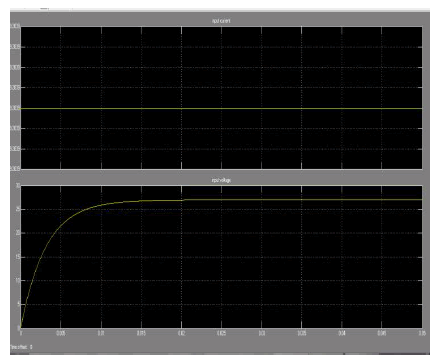
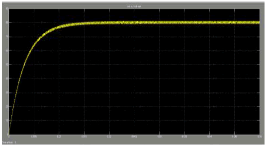
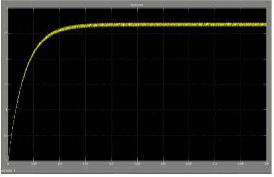
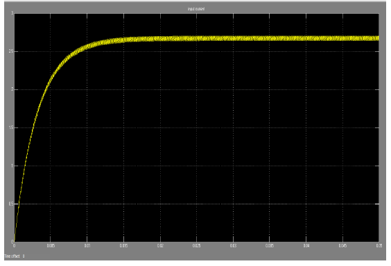
| By simulation the experimental results without and with resonant converters are obtained as shown below. |
INPUT CURRENT, VOLTAGE: |
 |
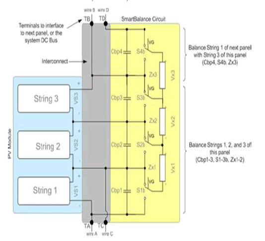 |
| Fig(6).Distributed converter circuit architecture |
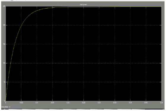
| The top level schematic representation of proposed converter configuration is represented with a single PV module. An extra stage is added to the circuit to extend the balancing function across a string of panels. Two additional terminals are required to provide positive and negative terminals to the adjacent strings of PV modules. The terminals are TA,TB,TC,TD. The above circuit is implemented and got results by using simulation. The corresponding input and output waveforms of the proposed system are obtained .And we achieve conversion efficiency was above 99% for gradient mismatch above 40%. |
INPUT POWERWAVEFORM: |
 |
OUTPUT VOLTAGE WAVEFORM: |
 |
OUTPUT CURRENT WAVEFORM: |
 |
OUTPUT POWER WAVEFORM: |
 |
CONCLUSION |
| Increasing the efficiency of plant and reducing complexity by the elimination of large magnetic components, is achieved by our proposed system that is tested in laboratory. The resonant converter performs parallel ladder architecture that it handles only mismatch power and turns off if there is no mismatch in the array. Thus, energy capture in the event of shading or mismatch is improved. vertical footprint less than 6mm is sufficient , cost is less as compare to traditional dc-dc converters. Reduces air volume in packaging and simplifies module co-integration. Insertion loss was consistently measured below 0.1% for a number of parts, and conversion efficiency was above 99% for gradient mismatch above 40%. The converter and voltage equalization strategy was shown to recover over 98% of available energy for gradient mismatch up to 40% including power point tracking ratio and converter power consumption. Hence ,by the proposed system high conversion efficiency is achieved . |
References |
|