ISSN ONLINE(2278-8875) PRINT (2320-3765)
ISSN ONLINE(2278-8875) PRINT (2320-3765)
Setu Garg1 ,Sandeep Tiwari2, Shantanu Singh Chauhan3 , Shivam Singh4 , Suhel Ahmad5
|
| Related article at Pubmed, Scholar Google |
Visit for more related articles at International Journal of Advanced Research in Electrical, Electronics and Instrumentation Engineering
In this paper, we have introduced a whole new ideaof video conferencing which has become increasingly widespread in the workplace. Currently , recording an important meeting under usual circumstances a person is hired to record the entire process of meeting, where issues of cost, convenience and security arises. A camera can also be installed at the edge of the conference room in order to capture all the employees and their conversation on the screen. Both the process force people to face in the direction of recording, which makes communication awkward. We have designed a system, to be placed of the centre of the table and uses microphones to locate the speaker and turns the camera to face them so that the emphasis is on the person currently speaking.
Keywords |
| video conferencing, microphone, camera , communication, recording. |
INTRODUCTION |
| In conventional video conferencing systems, a person is hired to record the entire process and thus all the recording is done manually by controlling the movement of the camera. This type of arrangement may not work effectively in a conference room where a number of persons aretalking at a given time. Secondly, in the web conferencing many cameras are mounted at fixed points thus forcing members of a conference to awkwardly facing towards the cameras throughout the meeting. Additionally, those sitting at the far end of the table are poorly captured on screen and thus it is not clear who is speaking. We aim to provide a rotating camera or voice tracing camera that will automatically track the speaker and points itself in that direction, allowing employees to carry on the normal meeting as if it were not even there.Since members of a meeting should be focused on the person speaking, our design would be valuable to companies that frequently use web conferencing. The concept will be accomplished using microphones and determining the delays between their respective incoming sound signals |
OBJECTIVE AND BENEFITS OF PROJECT |
| Making a simple electronic device which is capable of recording video session of a meeting or a conference. It eliminates the human effort, cost, and security issues (arising out of conventional method of human intervention). In accordance of the present invention, an automatic voice tracking camera system and method of operations are provided that substantially eliminate or reduce disadvantages and problem associated with previously developed video conferencing systems. According to one embodiment of the present invention, an automatic voice tracking camera system is provided. The system includes a camera operable to receive control signals for controlling a view of the camera. A microphone array includes a plurality of microphones. The microphone array is operable to receive a voice of a speaker and to provide an audio signal representing a voice. To generate from the audio signal speaker position data. A camera controller couples to camera, the camera controller is operable to receive the speaker position data and to determine an appropriate responsive camera movement. Also necessary control actions and needed to camera so that it automatically tracks the position of the speaker |
| Recording meeting process without cameraman and at a lower cost. |
| Provide a solution to best capture information exchanges (Q&A, argument or discuss) between two people between the meeting. |
| Auto-generated split-screen simplifies post production. |
LITERATURE REVIEW |
| In past years this concept has been evolved over the years the first of its kind with advanced work was in July 1995, by JoonyoulMaeng [1]. Infrared technology was employed to track the position of the speaker in the video conference in year 1996, by Brandstein, Michael S , Adcock , John [2]. Microphone array technology is been introduced into this whole concept which is wireless array of microphones in order to improve the reception of a sound and to allow location of the position of the speaker by Paul C. Meuse, Harvey F. Silverman [3]. An algorithm for determining talker location from linear microphone data array in year 1992 [4].Microphone arrays in large rooms [5].Computer-steered microphone arrays for sound transduction in large rooms ( J. Acoust volume 78 1985) .The quality of sound pickup in large rooms-such as auditoriums, conference rooms, or classrooms is impaired by reverberation and interfering noise sources [6]. These degradation can be minimized by a transducer system that discriminated against sound arrivals from all directions except that of the desired source. The signal-seeking transducer system is implemented as a dual beam “track while scan” array. It utilizes signal properties to distinguish between desired speech sources and interfering noise. This research report and derived equations were focused on using 4 microphones in a linear array to locate a sound source. |
CIRCUIT AND MAIN COMPONENTS |
| The main components of projects are as |
| 1) MICROCONTROLLER. |
| 2) MOTOR DRIVER. |
| 3) D.C MOTOR. |
| 4) MICROPHONE. |
| 5) CAMERA. |
A. MICROCONTROLLER |
| This module is the central control unit of the system. It collects data from the microphone array, decides in which direction the speaker is located, and controls the motor-control unit. It would tell the motor control unit how to direct the motor movement. a learning algorithm will be running on the MCU to determine the main speakers. |
| The microcontroller family we have used here is PIC 16F8--. The number 16 means that it is part of the family “MID-RANGE”. This is a microcontroller family 8 bit. The letter F means that the memory type is flash memory. The last three digits precisely identify the PIC. |
| Here we have used PIC16F877. It is a RISC (reduced instruction set computer) design. Only thirty seven instructions to remember. Its code is extremely efficient all the pic to run with typically less program memory than its larger competitors. It is low cost, high clock speed. |
| The memory of microcontroller is flash memory which |
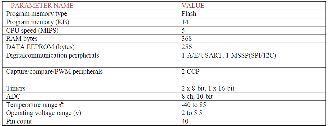 |
| is re-writable, much faster to develop on. |
| This powerful (200 nanosecond instruction execution) yet easy to program device makes it ideal for more advanced level A/D application in automotive , industrial, appliances and consumer applications. Operating frequency is 0- 20MHz. |
B.MOTOR DRIVER |
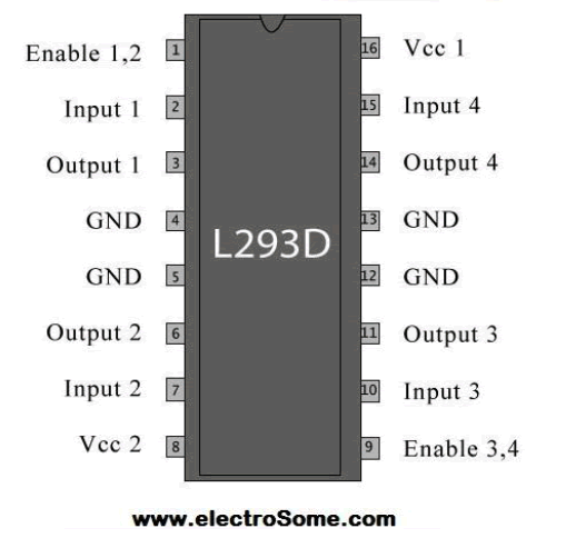
| Interfacing DC motors directly with microcontroller may affect the working of microcontroller an system due to the back emf of the dc motor. Hence motor driver are used to interface microcontroller and dc motor like IC L293D and L293. |
| The L293D is a popular motor driver IC that is usable from 6v to 12v, at up to 1 A total output current. The compact L293D motor driver makes it much more convenient to use. |
I.DATA SHEET CHARACTERISTIC |
 |
 |
 |
| H = Logic High , L = Logic Low , X = Doesn’t matter |
C. DC MOTOR |
| The selected version for moving the camera to face the speaker was a motor. At first stepper motors were considered but were rejected due to the possibility of the stepper motors missing a step due to inertia. Such a flaw would cause a loss of precision in the system and would require extra components to remedy. Servomotors, however have built in position feedback which allows such motors to correct any misstep they may make. Servomotors also have simpler control interfaces and electrical connections. This result in a need for fewer parts to use than stepper motors. |
| The motor is required to turn a full 360 degree and to complete a full 360 degree rotation in some seconds like 2 sec (velocity of 180 degree per sec). the motor also needs to have sufficient torque to move camera at the required speed. The GWS S 125 1T servo meets all of the requirements for the motor. This motor can move at no load 360 degree in 1.56 sec. it can produce a torque of 92 ounce-inches. The camera load was specified well within the range. Thus motor can handle any camera which meets the initial specifications and meets its own specifications. The motor also require a control signal and power source within the final product.We plan on producing our own driver instead of motor driver using a USB adapter and a digital-to-analog converter. The motor only draws 130mA under the camera load and operates between 4.8v and 6v DC. A USB port can carry between 500mA and 900mA @ 5V. Thus the motor is compatible with the USB connector device and the USB port of a computer and can function according to the specification. |
D. MICROPHONE |
| There are several different types of microphone: carbon, dynamic, crystal, capacitive (electret). Carbon microphones were one of the first to be invented and were used mainly in telephone applications. But they are very noisy as the carbon granules rattle when the microphone is moved and this type is being replaced by more advanced types. |
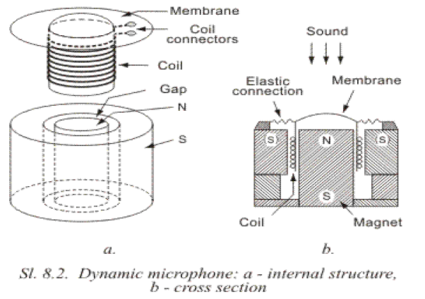
| Dynamic microphones are in wide use and their quality of reproduction is superb. They are used in the recording industry for music and speech where high fidelity is required. Basically they are exactly the same as a speaker, the only difference being the size. But their only limitation is the very low output. The internal structure is shown in figure 8.2. A paper cylinder, onto which fine copper wire is wound, is connected to a membrane which moves under the force of sound pressure created by the sound source. This coil is in a narrow gap with a high magnetic field created by a permanent magnet. When the coil moves in this magnetic field, it produces a voltage identical to the sound causing the movement. |
| Because of the low resistance (impedance) of a dynamic microphone, it usually needs a transformer so it can be connected to an amplifier (called a pre-amp). This transformer is usually built into the microphone's case, but if is absent, it is necessary to connect the microphone to a preamplifier with low input resistance. |
 |
E. CAMERA |
| For our camera we decided to use a pre-built webcam. These are designed to be used with computers and often have wide angle lenses, making them ideal for our product. We chose the webcam that meets all our specifications. That could be VGA camera or 1.3 megapixels. Both works with windows operating system. Finally the weight of the camera lies well within the range that motor can bear. The camera sits atop of the motor’s rotor and is connected to the computer through USB cable. This allows our camera output to be verified |
TESTING PROCEDURE |
| 1) Microphone array: The microphone array will be tested by sounding input from different position within 3-5 meter radius and the output will be monitored using oscilloscope. |
| 2) MCU: The microcontroller unit will be tested with the microphone array. Different test cases are taken as different people are talking at the same time. The output can be displayed on the monitor indicating the target direction of the camera. |
| 3) Motor Control Unit: it will be tested using the pre-programmed MCU and will give inputs to the motor control unit. |
| 4) Motor &Camera: The rotation of the motor can be tested using the input from function generator. We can use devices to measure angle of rotation. |
| 5) Computer: only the split screen function should be tested. We can simply input two video signals an see if can generate the split screen correctly. |
TOLERANCE ANALYSIS |
| The tolerance analysis mainly focuses on: |
| The error of voice source: |
| Detection caused by the geometry of microphone array and the factor of noise. The goal is to have the difference between actual source and the calculated source to be within 20 degrees. So that camera will still be able to capture the speaker in the frame if not centred in the frame. |
| The error of camera rotation: |
| We will analyse the cause of error of camera rotation if there is any. Again our goal is to limit the error within 20 degrees for the same reason as above. We will measure the tolerance by feeding the motor control with pre-calculated values so we know where the camera should be pointing at after the rotation. |
CONCEPT REDUCTION |
| The original idea we came up with was the wall-mounted camera system. One flaw we saw in the design was that the system would still require speaker to be at a, potentially far distance. Such a distance takes away from person-person correspondence when compared to the our system. |
| The next idea we eliminated from consideration was the fixed camera system. It required many cameras and microphones to be used, far more than by the rotating system. The extra component added too much to the cost of the system. If the system was built with fewer, but wider angle cameras; then the system stopped focusing on the speaker; it focussed on the group of people and is less likely to have speaker at the centre of the video. Using wireless microphone would have created the large equations which would obviously increase the project cost and efforts as alone microphones would be very expensive |
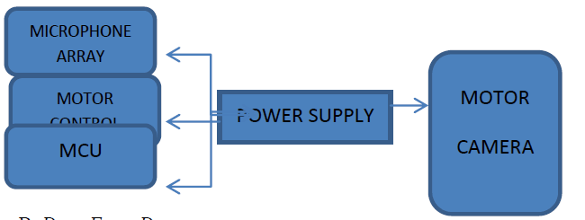
A. POWER SUPPLY DIAGRAM |
 |
B. DATA FLOW DIAGRAM |
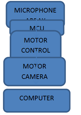 |
C.CIRCUIT DIAGRAM |
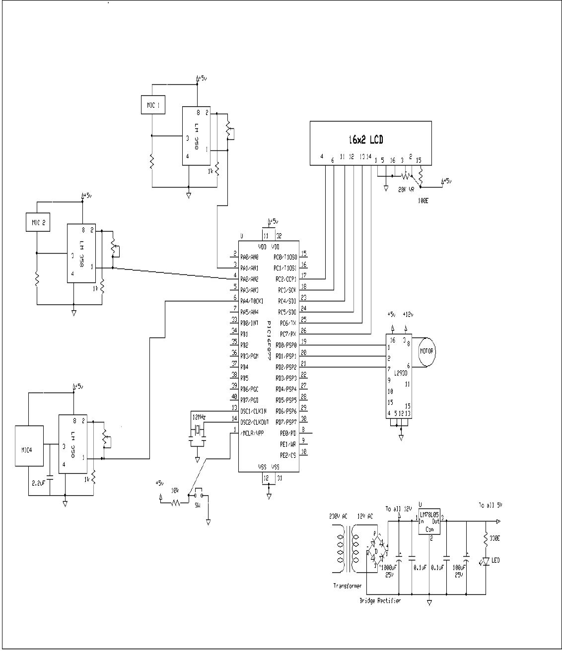 |
D.FLOW CHART DIAGRAM OF SYSTEM |
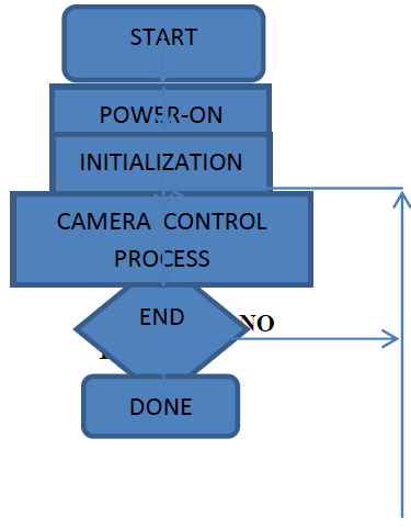 |
HAZARDAND FAILURE ANALYSIS |
| The microphones, resistors, capacitors, A/D converter, D/A converter, USB hub and USB adapter are all standard and they do not pose an abnormal threat to the environment. We are unable to find information about camera, motor but none of these materials came with warnings about being environmentally hazardous. |
| The only moving part of our system is the motor and camera which are under the plastic dome. This means that there is little chance of the safety issue with our product. Failure of our system means that the camera no longer rotates to the correct position. This can occur for multiple reasons, the most likely being bad connections. Since we are not working with large voltages or currents, these bad wires do not pose safety hazards. |
CONCLUSION |
| As a proof of concept, our design works pretty well. It can track a speaker within 10 degrees of their location in less than 3 seconds, which is well within the range of the camera. it also provide a good resolution display from the cameras and does good job of ignoring extraneous noises, which is crucial in determining who is speaking. With right adjustment our product or our design will be valuable to companies who frequently do web conferencing. |
| There are still several problems with our current design. The largest problem is that we currently use expensive components which hinder the range of the system. We got to use cheap components which make the system unable to detect a low volume speaker due to their small signal to noise ratio also our system for sending all of the audio and visual information to the computer incorporates many wires and ananalog to digital converter which is somewhat impractical and costly. Additionally we still have not designed a good way to make our design visually appealing while shielding the motor noise, which is necessary so that the conference participants are not distracted by it. |
| Ideally we need to test out the design with microphones of good quality that the ones we have used , also we need to encase our design in a structure that would insulate the motor noise and cover up the electrical components and wiring inside. A quieter motor would also benefit our design. Also we need some way of detecting when there are simultaneous speaker so that the camera does not oscillate back and forth between them. Ideally , it would just choose one of the speaker to track, probably the louder speaker, but we have not figured out a way to accomplish this. Finally, all of the wires should be grouped together with a rubber covering , so that they do not get tangled and are less visually obtrusive. |
ACKNOWLEGEMENT |
| We take this opportunity to express our deepest gratitude and appreciation to all those who have helped us directly or indirectly towards the successful completion of this paper |
References |
|