MANETs are self-configuring network of mobile routers and associated hosts connected by wireless links, the union of which form an arbitrary topology. The routers are free to move randomly and organize themselves arbitrarily, thus the network wireless topology may change rapidly and unpredictably. MANETs may also be defined as a network formed without any central administration which consists of mobile nodes that use a wireless interface to send packet data or MANET is a collection of mobile nodes with no fixed infrastructure, where some intermediate nodes should participate in forwarding data packets. MANETs have attracted a lot of researchers [1], [2] because of the growing popularity of mobile computing devices. The integration of mobile ad-hoc networks (MANETs) with the Internet and infrastructure based wireless networks have become an essential part of ubiquitous networking and has drawn the attention of researchers from industry and the networking community. Research on cross layer design in adhoc networks has recently attracted in significant interest [3], [4]. Initially, MANETs scenarios are deployed at places like business associates sharing information during meeting, military personnel coordinate emergency effort„s relief personnel coordinating efforts after a natural disaster such as hurricane, earthquake or flooding. Today, MANETs are required to support increasing demand for multimedia communication. The proposed research scheme FILDRC improves the end to end delay, throughput and also reduces the overhead to some limit. Traditional protocol selects the route with the smallest hop count. This can be implemented in military environment. It is observed that when load density is low, the link distance should be short; otherwise the link distance is large. Link distance is adjusted according to the network load. In this research paper we are concentrating mainly link distance on networks, end-to-end delay, and throughput in multi hop wireless networks.
Keywords |
| MANET, End-to-End Delay, Multi hop, FILDRC, Ubiquitous Network, Load Density. |
INTRODUCTION |
| Ad-hoc networks are revolutionize wireless communication in the present years. One of the fundamental tasks of
any ad-hoc network is that it must perform routing. Since the network is in general multi-hop, a routing protocol is
needed in order to discover and maintain routes between far away nodes, allowing them to communicate allowing
multi-hop paths. Most of the approaches proposed here are focused on the packet forwarding phase of a routing
protocol. The route to the destination is already known and the goal is to identify strategies that motivate nodes to
forward packets along this route. Relatively little attention has been devoted to the problem of simulating cooperation
in the route discovery phase of a routing protocol. Some of the important factor that need to be considered in designing
a routing protocols for MANETs are energy efficiency, minimum delivery latency, higher probability of packet
delivery, adaptability and scalability. Several routing protocols for MANETS have been proposed to cope with similar
problems and meet various application requirements. For instance, traditional proactive routing protocol eliminated the
initial route discovery delay, but could not perform efficiently in specific ad-hoc conditions [2] [3]. The reason is that
they waste the limited system resources to discover route that are not needed. On the other hand reactive routing
protocols have been proposed as an effective solution to the problems. The main advantage is that route discovery is performed only when there is request for communication between two network nodes. This issue is crucial in the design
of new routing protocols. To design such protocols, we have to look away from the traditional minimum hop routing
schemes. Traditional routing protocols designed for multi-hop wireless networks, e.g., the mobile ad-hoc network
(MANET), select a route with the smallest hop count. The end-to-end throughput in the route may not be the maximum
when the network has multiple link data rates, as a small hop number implies a large geographic distance (link
distance) for each hop. Due to the radio signal attenuation, this results in a low SNR at the receiving node and
consequently, a low available link data rate. Reducing the link distance by using routes with more hop counts can
increase the link data rate. However, this may not necessarily improve the end-to-end throughput because more nodes
have to be included in the routes. Analysis and simulation results show that changing the link distance affects the
network throughput. |
| Improving end-to-end throughput is required particularly for high-data-rate multimedia applications in multi-hop
wireless networks. However, it remains as one of the major challenges. Traditional multi-hop routing protocols are
designed for having the least hop count for an end-to-end connection. This reduces the contending parties that have to
share the upper-bounded bandwidth and, therefore, improves the throughput. The examples are ad-hoc on-demand
routing protocols, such as ad-hoc distance vector (AODV) routing protocol [5] and dynamic source routing (DSR) [6],
or position-aided routing protocols, such as greedy perimeter stateless routing (GPSR) [7]. The least-hop strategy works
if a fixed link data rate is used, because a smaller number of contending nodes means each of the nodes may have a
longer channel occupation time, which normally results in a higher network throughput. There have been existing
works that improve throughput in multi-hop networks by selecting routes according to metrics other than hop counts.
Link delay has been used in [8] and [9]. In [10], the probability of a successful packet delivery in each hop is the major
metric. In [11] cross layer design between PHY and MAC layer for power conversation based on the transmission
power control is used. Shortest path scheme is the most common criteria adopted by the conventional routing protocols
proposed for MANETS. The problem is that nodes along shortest paths may be used frequently and the batteries may
exhaust faster. The consequence is that the network may become disconnected leaving disparity in the energy and
disconnect the networks. Therefore the shortest path is not the most suitable metric adopted for routing decision. |
THE PROPOSED METHOD |
| In this section, we explore the idea of Farthest Intermediate Link Distance Reliability Cost (FILDRC) Based Cross
Layer Route Discovery for MANETS. The proposed FILDRC works on on-demand principle of route discovery and is
part of cross layer framework. FILDRC makes use of new cross layer interface, designed to combine the functionality
of the Routing layer with Application, Medium Access Control (MAC) and Physical (PHY) layer parameter to provide
the routing algorithm. FILDCR is evaluated by simulation to show how this scheme improves the network throughput.
In this paper, we first investigate and analyse the impact of link distance on end-to-end throughput in multi-rate multihop
wireless networks. Analysis and simulation results show that changing the link distance affects the network
throughput. To achieve a high network throughput, a proper link distance requirement has to be set for each hop,
depending on different parameters such as load density. Our target network is mobile ad-hoc network with low
mobility. Link distance has been considered for power savings in [12], [13], and [14]. In this paper, we focus on
improving the network end-to-end throughput from the link distance point of view. However, link distance highly
depends on network topology and it is difficult to control the actual link distance in a route. To make the research
results applicable for network protocol design, we further define the link distance requirements as the maximum length
for the link distance of a hop and evaluate the throughput when the link distance requirements are set as different
values. Since a hop can be included in a route only if its link distance is no more than this value, in this paper, the link
distance requirement is also called the maximum link distance or the maximum geographic hop distance. |
| We have considered the network that is less mobile and that has high density of nodes. For convenient analysis we
assume that every node in the network has the same radius. Every node knows the geographical position of itself and its
neighbours in its transmission radius which can be gained by using the global positioning systems (GPS). Messages
exchanged during transmission or receptions have a unique identity number which also consist of additional
information sender id and timestamps etc. MAC and the physical layer information are explored for routing. Here we
have concentrated on Link Distance [15] and Link Cost for the selection of the best routes. Link distance here is based
on the data rates. By this we select the routes with proper geographical distance between the nodes at the two ends of
the hop. Link Distance and Link Cost both are different because link distance highly depends on the network topology and it is difficult to control the actual link distance in a route. A hop can be included in a route only if its link distance
is no more than a defined value. Link cost is based on the cross layer design that rejects the paths with nodes having
less battery support than the specified threshold i.e. nodes below the battery support of 50 %. There have been lots of
researches to improve throughput in multi-hop network by selecting routes according to the metrics other than the hop
counts. Link delay has been used as the metric for calculation of the routes in [16], [17]. A simple cross layer design
between PHY and MAC layers for power conservation based on transmission power control is proposed in [18]. |
| Extensive researches have been done for developing core protocols at MAC and network layers since past few years.
Nodes depend on the batteries, so energy constraints have been focused a lot in MANETS. In [19] authors have
proposed a new mechanism to reduce the power consumption, while increasing channel utilization. This approach tries
to adapt the power level used by a mobile host to transmit data packets as a function of the relative distance to the target
node according to the strengths at which RTS/CTS packets are received. In [20] routing protocol has been proposed for
minimum energy broadcasting dedicated to static MANETs. The MTPR (Minimum Total Transmission Power
Routing) [13] was developed to minimize the total transmission power consumption of the nodes participating in the
route, while in [21] Min-Max Battery Cost Routing (MMBCR) considers the remaining power of the nodes as the
metrics for acquiring routes in order to prolong the lifetime of each node. In [23], [24] authors have used the concept of
sending the packets to the maximum farthest intermediate nodes only, once the route is discovered. In this research
work, for data transmission we are using the concept of [22], [23]. |
SMALL NETWORKS |
| Two cases occur that will effect end-to-end throughput when the network size is small or large. In a network nodes
are randomly located, some node that wants to send data acts as the source and receiver node is the destination. In small
size network it may be possible that the source want to send data to destination node and that destination is in the radio
range of the source node. So the data can be sent directly to that destination node. First of all the possible routes are
discovered to reach the destination. All these routes may have different link distance; we first select the routes that have
the minimum link distance and calculate the corresponding end-to-end throughput. This value is not more than mobile
ad-hoc transmitting range. The link distance is equal to the geographic distance between the source and the destination
divided by the minimum number of farthest intermediate node. In a network that has i connections, let N = {N1, N2...
Ni} be the geographical distances between the sources and their destinations for these i connections. Let h = {h1, h2...
hi} be the number of intermediate hops in each connection, which is also the vector of the number of transmitting
(contending) nodes in the routes. Since every node is within the CZ (carrier sense zone) of any other node in the
network, the overall number of nodes that will contend for the channel is D. Let d = {d1, d2... di}, where dj is the link
distance for each intermediate hop in the connection j, and dj = Dj / hj. Let c = {c1, c2,...., ci} be the set for all the data
rates for these connections. Using Shannon„s theory and the two-ray ground radio propagation model, the highest
available data rate in every link for this connection (which is defined as cj) is |
 (1) (1) |
| As CSMA is used, when a node is transmitting a packet, all other nodes can sense it and they will not attempt to
transmit. Therefore there is no chance of channel interference. Packets with different size have different transmitting
rate and time taken. The amount of time a node occupies a channel for its purpose depends on the data rate. The end to
end throughput is defined as the number of bits that are successfully transmitted by any node in the connection. |
LARGE NETWORKS |
| In this section we are briefly discussing about the effect of the link distance on the end to end throughput when the
network size is large. In this case the source and the destination are located far away. The route that is discovered has
large number of hops and therefore large number of farthest intermediate nodes. A source that has data to forward i.e.
active node has to contend with all other active nodes within its carrier sense range to access the channel. As the
distance between the source and destination is large, most of the active nodes in its carrier sense are farthest
intermediate node. As the number of connection increases throughput decreases as number of connection in the
network increases. It can be concluded that when the network size is small and it is lightly loaded, it is possible to improve the through put by reducing the link distance, because the data could be send directly to the destination node
without the help of the intermediate node. In large network size ( heavily loaded) it is more important to keep the
number of contending nodes small by using the concept of sending the data to the farthest intermediate node in the
radio range of the sender. |
FILDRC ROUTING |
| It is assumed that initially all the batteries are fully charged. When the source node wants to transmit data, it broad
cast the route request message once and maintains its routing table, due to which when the source node sends the data
packet it only needs to know its neighbour node. As the paths are discovered whenever they are needed it reduces the
overhead. Although some information is needed to be calculated to store the record in the routing table the energy
expense is less as compared to the transmit and receive energy. The format of the route request message (R-REQ) is
shown in Table 1. The Source ID contains the node ID of the message to destination, Sequence Number is the packet
sequence, Link Distance (Hop Count) is the number of nodes between the source and the destination node, Energy
threshold gives information about the energy level for the node to take part in transmission and reception, i.e. every
node should have battery support above 50% then only it can take part in routing. Signal strength threshold is the
minimum distance the node selected for data transmission has to be located in order to receive all the data transmitted
to that particular node. Destination ID is node where the data has to reach. |
| For data transmission source node S wants to transmit to destination node D. If the destination node is in the
transmission range of Source S then, as the source node has the information about the neighbour, it can send the data
directly to that node. If the destination node is not in the sensing range, source S broadcast the route request message
RREQM. Then the shortest path to reach the destination is obtained from the concept of paper [22]. After establishing
the different paths, the paths are stored in the routing table as shown in table 2. |
| When we have discovered all possible paths from S to D, initially we consider the shortest path for data transmission.
In the traditional routing shortest path is considered for transmission without any checks on that route, which may
create problems like if node battery deplete or any problem like change of topology, the guarantee that data would
successfully reach destination decreases. Shortest path concept also introduces problems that due to again and again use
of the same route it will heavily load those nodes on the path even when there exist other feasible paths. We have tried
to find a much feasible path instead of just the shortest path. For feasibility analysis we check for link cost i.e. battery
support of all the node for the selected route. The route that is selected for data transmission all the nodes in that route
should have remaining battery support more than 50 %. Those nodes whose remaining battery supports less than 50%
are dropped and that route will not be considered as feasible path. Traditional shortest path routing may create problem whereas heavily loaded nodes and feasible routing algorithm necessarily use long path. This scheme is divided into
three major steps |
| Receiver in the transmission range of sender |
| All possible route discovery, calculation of link distance |
| Link Reliability Cost Analysis : Reliability analysis and Cost Analysis |
| ALGORITHM FOR FILDRC |
| The algorithm can be laid down as under: |
| 1. If receiver is in the transmission range of sender. |
| 1.1 Send data to the receiver. |
| 2. Discover all possible routes. |
| 3. End-if. |
| 4. Compute the link distance. |
| 5. Choose the route that has minimum link distance. |
| 6. Does it pass the cost analysis and reliability analysis? |
| 6.1 Send the data. |
| 7. Go to step 4 to choose the next higher link distance |
| 8. End while. |
RECEIVER IN THE RADIO RANGE OF SENDER |
| Suppose the source S has data to send to the destination D. If the receiver is in the radio range or sensing range of the
sender, then without opting for using the intermediate range, source S would directly send the data to D node. |
ALL POSSIBLE ROUTE DISCOVERY, CALCULATION OF LINK DISTANCE |
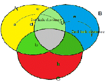
| Link distance is the distance from the source node to first farthest intermediate node in the radio range. It would be
termed as 1st link distance. We calculate to reach from source to destination how many link distances are required. It
can be well understood from figure 1a given: From figure 1a we can observe that for source node {a} the other node
in the radio range are {c, d, b, g}, but we send the data to the farthest intermediate node {g} and it is denoted as the 1st
link distance. Now {g} sends data to {f} and it is called the 2nd link distance. In this way when the node wants to send
the data first the entire possible route to reach the destination node is calculated. Then the link distance is calculated.
The link with minimum link distance is chosen for transmission. When the destination is not in the radio range of the
sender, intermediate nodes strategy is to be chosen to send the data. The entire possible route is discovered to reach the
destination and then the link distance is calculated. After the calculation of link distance, the route that has the
minimum link distance is chosen to forward the data after cost and reliability analysis. We have considered the network
that is less mobile. Mac and the physical layer information are explored for routing. Link Cost and Link distance both
are different because link distance highly depends on the network topology and it is difficult to control the actual link
distance in a route. The link distance for different routes can be different. The next node is selected not only based on
whether a node can process a packet most closely to the destination but also on whether the node is reliable and battery
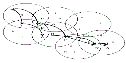
capacity is not low. In the figure 1b Source A wants to send data to the destination X. Different routes are searched. We
are comparing 2 routes in the below diagram. Route 1 has link distance 4 = {A, Z, P, W, X} & Route 2 has link
distance 5 = {A, Y, O, P, W, X}. So we select route 1 which has the minimum link distance. This calculation takes
comparatively more time but at the same time it increases the guarantee for successful data delivery chances. After that,
on that route, reliability and cost analysis is performed. |
LINK RELIABILITY ANALYSIS |
| Here route request from the source is accepted by a node only if its reliability is high, otherwise it is discarded. In
addition to the other advantage this approach decreases number of packet loss during transmission. Reliability (R) level
of each node has to be calculated. We mainly concentrate on the reliability check for those farthest intermediate nodes because they would be forwarding the data, therefore they should have high reliability. Reliability is calculated
based on the remaining energy of the node periodically. We are not considering idle and sleep mode. After every
transmission the remaining energy is calculated. When the remaining energy goes below 50 %, that particular node
would be discarded. The consumed energy for transmission and reception mode can be calculated as below: |
| In transmission mode power consumed for transmitting a packet |
| Consumed energy = transmitting power (Pt) * transmission time (T) (2) |
| In reception mode power consumed for receiving a packet |
| Consumed energy = reception power (Pr) * reception time (T) (3) |
| where |
| Reception time = Data size/ Data rate (4) |
| Remaining energy of each node is calculated as from equation 2 and 3. |
| Left Energy or remaining energy = Current Energy – Consumed Energy (5)
Relationship between reliability energy and reliability value is shown by table 3. On the basis of remaining energy of
the node, that node is given chance to participate in routing. Those nodes which are having remaining energy up to 50
% left can participate in routing. |
| If the reliability is very low, the node rejects the route request. If the reliability is medium the route request is then
forwarded to next farthest intermediate node. When the route request reaches the destination, it checks. If it is found
that every node has high reliability, this route is selected as the route for sending the data. |
COST ANALYSIS |
| Link Cost is based on the cross layer design that rejects the paths with nodes having less battery support than the
specified threshold. Link distance is highly dependent on network topology and it is very difficult to control the link
distance. For the calculation of the link cost the information that is needed is (i) transmit power (ii) remaining battery
capacity of the node at any time t ( can be obtained from above equations) (iii) Fully charged battery. Link cost can be
calculated as follows [31] |
 |
 |
 |
| Both FILDRC and AODV are reactive on demand route selection protocol. Reactive protocols seek to set up routes ondemand.
If a node wants to initiate communication with a node to which it has no route, the routing protocol will try to
establish such a route. In case of failure of primary route, AODV initiates a rediscovery process while in the case of
FILDRC an alternative route is always available in all nodes from source to destination. |
ROUTE MAINTENANCE |
| Route maintenance is initiated whenever the best feasible route that is selected to route between source and
destination is broken or changed due to reasons like node mobility, battery failure. Once the best feasible route
selection is done, destination node starts a timer to keep track of the availability of selected route. If data packets from
source do not reach the destination node and the timer expires, it is assumed that the selected route between the source
and the destination is lost or broken. In this case destination node selects alternative best route and initiates the process
again. FILDRC avoid unnecessary flooding and overloading of the ad-hoc network. In route maintenance phase
FILDRC do not use “HELLO” messages, instead it goes for an alternative path that is available. |
SIMULATION AND RESULTS |
| The performance of our algorithm is evaluated using discrete event simulator. The simulation of the ad-hoc network
for 100 nodes in a 1000 m area is considered. Initially all the battery is charged fully. When the process starts the initial
energy is progressively reduced by data transmission/ reception. When the battery totally discharges the node cannot
take part in the communication process. Each node has a radio propagation range of 250 meters and channel capacity
was 2 Mb/s. Performance metrics are node energy consumption which is the average energy spent by node to transmit
data from source to destination. Data delivery ratio is number of data packets sent by the source and the number of data
packets received by destination. Average time is the time between the data packet send by the source and the time the
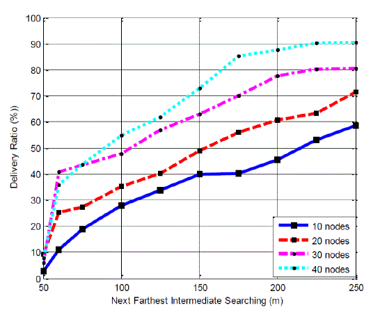
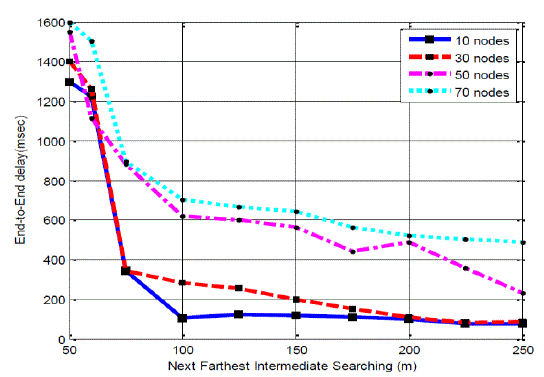
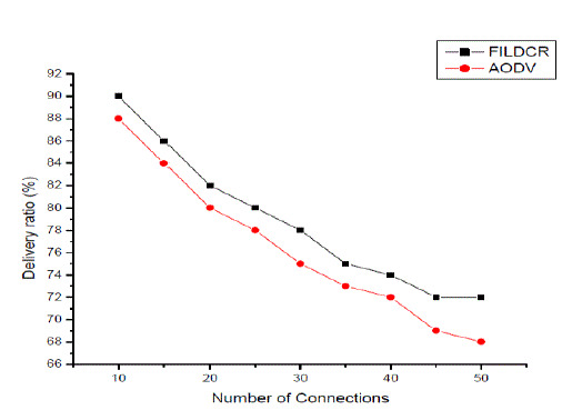
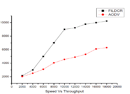
destination receives it. Figure 3 gives the compares speed and the throughput. Figure 4 shows number of hops in route
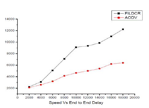
which reduce the energy consumed for transmission. The average packet delay for FILDRC and AODV is shown in
figure 5. Figure 6 describes about the speed and the end-to- end throughput. Table 5 shows about the simulation
parameters. Figure 2 shows the network with light load of 10 connections, a medium load of 30 connections, a heavy
load of 50 connections and a very heavy load of 70 connections. In figure 3 and figure 6 shows end-to-end delays are
observed in paths. At low load, end-to-end delay is lower than high load networks. This delay includes all the delay
caused in route discovery latency, transmission delay etc. When the load increases, delay increases as there are too
many request sender. Figure 4 shows that total numbers of bytes that have been successfully delivered to the destination
nodes. Better throughput is observed as it integrates cross layer design with it. Figure 5 is the ratio of the data packets
delivered to the destination node. |
CONCLUSION |
| This research work FILDRC with cross layer approach improves the end to end delay, throughput and also reduces
the overhead to some extend. Simulation results prove that FILDRC is better than AODV. Traditional protocol selects
the route with the smallest hop count. This can be implemented in military environment. It is observed that when load
density is low, the link distance should be short; otherwise the link distance is large. Link distance is adjusted according
to the network load. For better performance end-to-end delay and throughput must be improved. Hence, in this paper,
we have discussed about the link distance on networks, end-to-end delay and throughput in multi hop wireless
networks. The future research work would be upgrading an efficient cross layer design considering very high mobility
issues in MANET. |
| |
Tables at a glance |
 |
 |
 |
 |
 |
| Table 1 |
Table 2 |
Table 3 |
Table 4 |
Table 5 |
|
| |
Figures at a glance |
 |
 |
 |
 |
| Figure 1a |
Figure 1b |
Figure 2 |
Figure 3 |
 |
 |
 |
| Figure 4 |
Figure 5 |
Figure 6 |
|
| |
References |
- IETF MANET WG (Mobile Ad-hoc NETWORK), www.ietf.ora/html.charters/manet- charter.html
- C.E Perkins, E.M Belding-Royer, and S.R Das, Ad-hoc On-Demand Distance Vector (AODV) Routing?, IETF Internet Draft, draft-ietf-manet-aodv-13.txt.
- S Shakkottai, T. S. Rappaport, and P. C. Karlsson, Cross- layer design for wireless networks?, IEEE Communications Magazine, vol. 41, pp. 74, Oct 2003.
- V Srivastava, M Motani, Cross-layer design: A survey and the road ahead?, IEEE Communications Magazine, Vol. 43, Issue 12 , pp. 112-119, Dec.2005.
- C. Perkins, E. Royer, Ad-hoc on-demand distance vector routing?, in Proc. 2nd IEEE Workshop Mobile Computing System Application, pp. 90âÃâ¬Ãâ100, 1999.
- D. Johnson and D. Maltz, Dynamic source routing in ad-hoc wireless networks?, in Proc. ACM SIGCOMM-Computing Communication Review, pp. 153âÃâ¬Ãâ181, 1996.
- B. Karp and H. T. Kung, GPSR: Greedy perimeters stateless routing for wireless network,? in Proc. ACM/IEEE Mobicom, , pp. 243âÃâ¬Ãâ254, 2000.
- B. Awerbuch, D. Holmer, and H. Rubens, High throughput route selection in multi-rate ad-hoc wireless networks?, in Proc. 1st Working Conf. WONS, pp. 253âÃâ¬Ãâ270, 2004.
- S. Sheu, Y. Tsai, and J. Chen, MR2RP: The multi-rate and multi-range routing protocol for IEEE 802.11 ad-hoc wireless networks?, Wireless Network, vol. 9, no. 2, pp. 165âÃâ¬Ãâ177, 2003.
- D. S. J. De Couto, D. Aguayo, J. Bicket, and R. Morris, A high throughput path metric for multi-hop wireless routing?, in Proc. MobiCom, , pp. 134âÃâ¬Ãâ 146,2003.
- B Ramachandran, S Shanmugavel, A Power Conservative Cross Layer - AODV Layer Design for Mobile Ad- hoc Networks?, Information Technology Journal, Vol. 4, No.2, pp. 125-131, 2005.
- S. Banerjee, A. Mishra, Minimum energy paths for reliable communication in multi-hop wireless networks?, in Proc. ACM/IEEE MobHoc, pp. 146âÃâ¬Ãâ156, 1996
- K. Scott, N. Bamboos, Routing and channel assignment for low power transmission in PCS?, in Proc. ICUPC, pp. 498âÃâ¬Ãâ502, 1996.
- S. Singh and C. Raghavendra,,PAMAS,Power aware multi-access protocol with signalling for ad-hoc networks?, ACM Communication Review, Vol. 28, No. 3, pp. 5âÃâ¬Ãâ26, Jul. 1998.
- Wu Xiaoxin, Gang Ding, Zhu Wenwu, Load Based Route Discovery Through Searching Range Adaptation for MANETS Through put Improvement?, IEEE Transactions on Vehicular Technology, Vol. 58, No.4, 2009.
- S Singh, C Raghavendra, PAMAS-Power aware multi-access protocol with signalling for ad-hoc networks?, ACM Communication Review, Vol.28, No.3, pp. 5-26, 1998.
- B Awerbuch, D Holmer, H Rubens, High throughput route selection in multi- rate ad-hoc wireless networks?, Proc. 1st working Conf. WONS, pp.253-270, 2004.
- S Sheu, T Sai, Chen J. MR2RP: The multi-rate and multirange routing for IEEE 802.11 ad-hoc wireless network?, Wireless Network, Vol.9, No.2, pp.165- 177, 2003.
- S.L Wu, Y.C Tseng, J.P Sheu, Intelligent Medium Access for Mobile Ad-hoc Networks with Busy Tones and Power Control?, Proceedings of the International Conference on Computer Communications and Networks, 1999.
- Peng-Jun Wan, Gruia Calinescu, Xiang yang Li , Ophir Frieder, Minimum-Energy Broadcast Routing in Static Ad-hoc Wireless Networks?, Proceedings of IEEE INFOCOMM, 2001.
- S Singh, M Woo, C. S. Raghavendra, Power aware with Routing in Mobile Ad-hoc Networks?, Proceedings of Mobicom, 1998.
- Kanojia Sindhuben Babulal, Rajiv Ranjan Tewari,Cross layer Energy Efficient Routing (XLE2R) for Prolonging Lifetime of Wireless Sensor Networks, Proceeding of IEEE-ICCCT, pp. 70-74, Sep. 2010.
- Kanojia Sindhuben Babulal and Rajiv Ranjan Tewari,E2XLRADR (Energy Efficient Cross Layer Routing Algorithm with Dynamic Retransmission for Wireless Sensor Networks), International Journal of Wireless & Mobile Network, Vol. 2, No. 3, pp. 167-177, Aug. 2010.
- Lu Xianling, Sun Yaming, Yu Jiming, Yan Wenxu, An Energy Efficient Cross Layer Routing Algorithm for Wireless Sensor Networks?, IEEEICIEA 2006.
- P.Gupta, P.R.Kumar, The capacity of wireless networks?, IEEE trans. Inf. Theory, Vol.46, No.2, , pp.388-404, Mar. 2000.
- C.R. Lin, J.-S. Liu,?QoS routing in ad-hoc wireless networks?, IEEE Journal Selected Areas in Communications, Vol.17, No.8, pp. 1426-1438, 1999.
- J. Broch, D. A. Maltz, D. B. Johnson,Y.-C. Hu, and J. Jetcheva, A performance comparison of multi-hop wireless ad-hoc network routing protocols, in Proceedings of 95 the Fourth Annual ACM/IEEE International Conference on Mobile Computing and Networking (Mobicom98), ACM, Oct. 1998.
- E. Royer and C. Perkins, Multicast Operation of the Ad-hoc On-Demand Distance Vector Routing Protocol?, ACM/IEEE International Conference on Mobile Computing and Networking (MOBICOMâÃâ¬Ãž99), pp 207-218, 1999.
- Nesargi and R. Prakash, Distributed Wireless Channel Allocation in Networks with Mobile Base Stations?, IEEE Conference on Computer Communications (INFOCOM âÃâ¬Ãž99), 1999
- L. Breslau, D. Estrin, K. Fall, S. Floyd, J. Heidemann, A. Helmy, P. Huang, S. McCanne, K. Varadhan, Y. Xu, and H. Yu, Advances in network simulation?, in IEEE Computer, Vol. 33, No. 5, pp. 59-67, May 2000.
- M. Maleki, K. Dantu, and M. Pedram,,Power-aware Source Routing in mobile ad-hoc networks?, Proceedings of ISLPED âÃâ¬Ãž02, Monterey, CA, pp. 72-75, Aug. 2002
|