International Journal of Advanced Research in Electrical, Electronics and Instrumentation Engineering
ISSN ONLINE(2278-8875) PRINT (2320-3765)
ISSN ONLINE(2278-8875) PRINT (2320-3765)
| Ajinkya Chouthai1, Rathin Karhu2, Soham Kulkarni3 UG Student, Dept. of E&TC Engineering, PVG’s COET, Pune, Maharashtra, India |
| Related article at Pubmed, Scholar Google |
Visit for more related articles at International Journal of Advanced Research in Electrical, Electronics and Instrumentation Engineering
This paper illustrates a new method of measurement of revolutions per minute (RPM) using TSOP IR receiver. The principle of opto-coupler is used in measuring RPM in the infra-red (IR) range wherein TSOP is the IR receiver. New terms for RPM measurement have been defined which assist in calculating maximum RPM. The maximum RPM that can be measured using this method is over 140,000 for TSOP 1756.This method of RPM measurement can be used having significant advantages like compact size, accuracy, wide range of values and low cost.
Keywords |
| Absolute Maximum Measureable RPM (AMMR), Angle of Slot, Burst Length, Disk with slot, Relative Maximum Measureable RPM(RMMR), Slot-Disk Ratio, TSOP |
INTRODUCTION |
A. Revolution per minute : |
| Revolutions per minute (abbreviated rpm, RPM, r/min, or r·min−1) is a measure of the frequency of a rotation. It annotates the number of turns completed in one minute around a fixed axis. It is used as a measure of rotational speed of a mechanical component. |
| RPM measurement is important when controlling or monitoring the speed of motors, conveyors, turbines, etc.[1].In vehicles RPM measurement assumes critical importance. Speeds above maximum safe operating speed are typically indicated by an area of the gauge(tachometer in vehicles) marked in red, giving rise to the expression of "redlining" an engine — revving the engine up to the maximum safe limit. Thus controlling of the engine requires foreknowledge of the RPM whether it is done manually or automatically, mechanically or electronically.RPM measurement is required also for traffic engineering wherein a test vehicle is equipped with tachometer and conducts test runs. |
B. Principle of opto-coupler/opto-isolator : |
| An opto-coupler (opto-electronic coupler) is essentially a photo-transistor/photo-diode and an LED combined in one package. When current flows in the LED, the emitted light is directed to the phototransistor/photo-diode, producing current flow in the transistor/diode. The coupler may be operated as a switch, in which case both the LED and the photo-transistor/photo-diode are normally off. A pulse of current through the LED causes the transistor/diode to be switched on for the duration of the pulse. Because the coupling is optical, there is a high degree of electrical isolation between the input and the output terminals, and so the term opto-isolator is sometimes used. The electrical isolation allows a low voltage dc source to control high voltage circuits.[2] |
C. TSOP IR receiver : |
| For this project TSOP (Thin Small Outline Package) IR (Infrared) receiver was used in place of photo-diode/phototransistor. TSOP 1756 was the part number. |
| TSOP 17XX series are miniaturized receivers for infrared remote control systems. The XX in the series denotes the carrier frequency (in kHz) of a suitably modified optical data at which the particular receiver gives logic LOW output.[3] |
| The suitable data format for the TSOP receiver is as follows: |
| 1. Carrier frequency should be close to the center frequency of the band pass.(e.g. 38 kHz for TSOP 1738) |
| 2. Burst length should be 10 cycles/burst or longer. |
| 3. After each burst which is between 10 cycles and 70 cycles a gap time of at least 14 cycles is necessary.[3] |
| The advantages of TSOP IR receivers are: |
| 1. Photo-diode and pre-amplifier in one package. |
| 2. Low power consumption |
| 3. High immunity against ambient light. |
| 4. Internal filter for PCM frequency. |
| 5. TTL and CMOS computability. [3] |
| The internal block diagram is shown in Fig.1. |
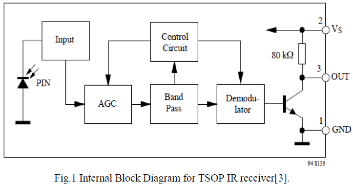 |
| This figure shows the photo-diode that is actually used in photo-detection and the subsequent amplifier circuit which amplifies the signal. |
HARDWARE IMPLEMENTATION |
A. Method of measuring RPM : |
| The opto-coupler method will be used for measuring RPM. An IR LED will be used as a transmitter with suitable pulse generator. TSOP 1756 will be used as the receiver which will give output LOW when IR light is incident upon it as it is active LOW.[3]. |
| A circular disk with a slot (which is part cut from the disk) is mounted on the shaft whose RPM is to be measured. The disk will be rotating with the shaft. The construction of this disk is shown in Fig.2. |
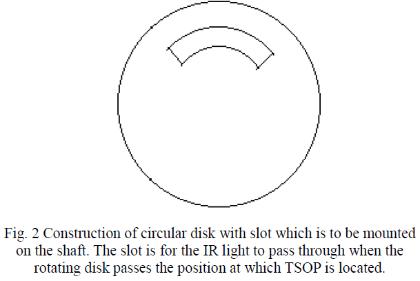 |
| IR LED & TSOP receiver will be at the same level with the rotating disk in between. With each rotation the slot passes in front of the TSOP receiver once, thereby allowing IR light to be incident on TSOP giving a LOW output which can be processed by the microcontroller. |
B. IR led with 555 astable timer IC : |
| For TSOP the incident light must have data format which is a square wave with frequency of 56 kHz (for TSOP 1756) [3]. |
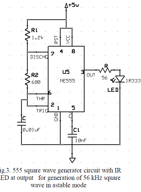
| To generate a square wave of IR, the IR LED must have a source signal of 56 kHz square wave. To generate a square wave IC 555 can be used in astable mode.[4]. |
| The 555 circuit can be designed using the equations |
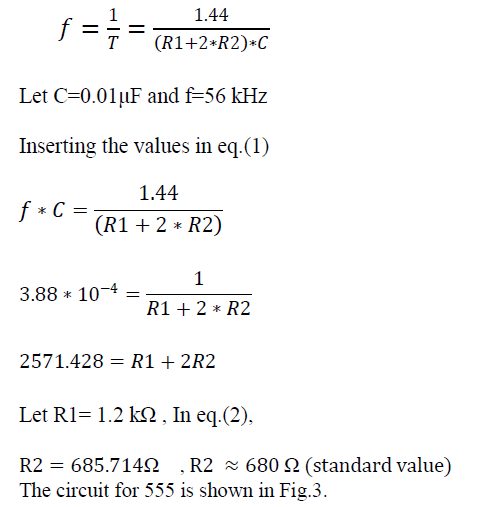 |
 |
C. TSOP IR receiver interfacing circuit : |
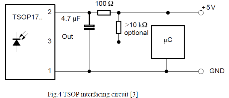
| The TSOP can be interfaced with the microcontroller as shown Fig.4.according to datasheet. |
 |
IMPORTANT DEFINITIONS |
| Definition 1- Burst Length: It is the time period in cycles per burst for which the optical data is continuously switching ON & OFF at a fixed frequency. |
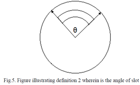
| Definition 2- Angle of Slot: It is the central angle subtended by the circular slot in the circular disk as shown in Fig.5. |
 |
| Definition 3- Slot-Disk Ratio: It is the ratio of angular distance occupied by the circular slot and the angular distance of the remaining part of the circular disk. |
| Also,it is the ratio of angle of slot and (360°-angle of slot) |
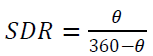 |
| Where θ is the angle of slot in degrees and SDR is the slot-disk ratio from definition 3 |
| Definition 4- Relative Maximum Measureable RPM: It is the maximum possible RPM which can be measured by the circuit for a particular slot-disk ratio at a particular carrier frequency. It is abbreviated as RMMR. |
| Definition 5- Absolute Maximum Measureable RPM: It is the It is the absolute maximum possible RPM which can be measured by the circuit for a particular carrier frequency. The absolute maximum measureable RPM for a circuit can only be measured for a one particular slot-disk ratio. |
CALCULATIONS FOR CIRCUIT |
A. Part number of TSOP used : |
| For the calculations TSOP 1756 is considered which has responds to a IR optical data having 56 kHz carrier frequency.[3] |
B. Important considerations : |
| For the TSOP to give a LOW output the burst length must be at least 10 cycles/burst [3] i.e. at least 10 cycles of optical data must pass through the slot to be incident on the TSOP IR receiver. Similarly between two successive bursts a burst length of at least 14 cycles/burst is necessary. [3] i.e. at least 14 cycles of optical data must be incident on the remaining part of the disk during which output of TSOP receiver will be HIGH. |
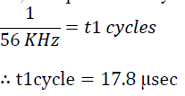
C. Time period of one cycle : |
| As TSOP 1756 is being used the carrier frequency of optical data is 56 kHz. |
| So, time period of 1 cycle will be |
 |
D. Calculation for relative maximum measurable rpm RMMR : |
| Let the angle of slot as defined in definition 2 be θ1 |
| As already shown in section 4.2 at least 10 cycles must pass through θ1 Considering this information |
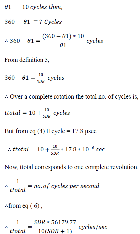 |
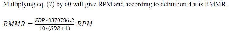 |
E. Calculations for Absolute Maximum Measureable RPM (AMMR) and its corresponding Slot-Disk Ratio (SDR) : |
| As already stated in section 4.2 minimum 14 cycles of the optical data must lie in the remaining part of the disk. To get AMMR let us consider that only 14 cycles lie in the remaining part of the disk so that minimum no. of cycles i.e. 24 cycles of the optical data lie in one complete rotation. |
| From eq. (5) |
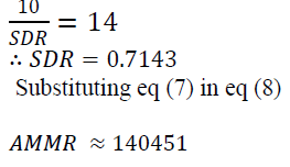 |
| Thus from eq (9) the Absolute Maximum Measurable RPM for TSOP 1756 is approx. 140451. |
F. Resolution : |
| As there is only one slot the circuit can measure RPM only when one complete revolution is completed, hence the resolution of this method is 1 rpm. |
CONCLUSION |
| This method of RPM measurement gives many advantages over traditional methods. |
| Firstly, size of the circuit is very compact as the components of the circuit are small and the entire circuit can be enclosed in an enclosure and attached to a shaft, |
| Secondly, this method generates accurate readings as the circuit is highly noise resistant. External signals and light do not affect readings .In fact this circuit was tested in bright sunlight and it gave negligible deviations in readings compared to testing in optically dark conditions. |
| Thirdly, the cost of the circuit is very low and the components are easily available. |
| Lastly, the maximum range of RPM is significantly higher than most of the present methods. |
| This method can easily be deployed as tachometer in various vehicles. It can be modeled as separate RPM counter product. |
FUTURE SCOPE |
| The resolution of this method is 1 RPM. It can be improved using multiple slots instead of a single slot. The Absolute Maximum Measurable RPM (AMMR) can be further increased using TSOP 18XX series which has lower burst length than 17XX series. [5] |
ACKNOWLEDGMENT |
| The authors would like to thank Prof. N.P. Deshpande of PVG’s College of Engineering and Technology, Pune for guiding in this project.. |
| The authors would also like to thank their colleagues Mr.Bhavin Shah for using this method in a robotics competition and confirming the accuracy of this method and Mr.Mihir Phatak for guiding in research work. |
References |
|