Keywords |
| Client/Server NMS, Mobile agent based NMS, SNMP request, SNMP response, WDM. |
INTRODUCTION |
| Network Management is performed on the basis of basic client server model. In these models Network manager acts
as client, it send request to managed devices to get information about their current status and managed devices acts as
server which send response to manger according to their request. These client server models having their prone and
cons. The client server models inherent some issues which have a major effect on network resource are Centralized
Management, Scalability, Bandwidth wastage, Response time, Fault Tolerance. Mobile Agent models handle these
challenges of client server based network management model. Mobile agent is an autonomous entity that visits to
remote node to perform some operation locally according to status of remote node. |
| In mobile agent based approaches the management activities are not performed at centralized node but distributed to
different mobile agent. |
| These mobile agents visit managed node and perform manage operation on remote node. MA resolves C/S issues of
Network Management Models as Distributed Management, Scalability, Efficient Bandwidth Utilization, Reduce
Response time, Fault Tolerance. |
| Mobile Agent models handle these challenges of client server based network management model. Mobile agent is an
autonomous entity that visits to remote node to perform some operation locally according to status of remote node. |
| In mobile agent based approaches the management activities are not performed at centralized node but distributed to
different mobile agent. |
| These mobile agents visit managed node and perform manage operation on remote node. MA resolves C/S issues of
Network Management Models as Distributed Management, Scalability, Efficient Bandwidth Utilization, Reduce
Response time, Fault Tolerance. |
RELATED WORK |
| Modern days, client server based network management models suffer from the well-known problems of centralized
system i.e. lack of distribution. The client/server based Network management system leads to centralized system, based
on SNMP or CMIP management protocol, which does not solve the problem of scalability and flexibility. SNMP V2
also adds improvements in the area of manager to manager communication. GetBulkRequest has been added to retrieve large data amounts by a single request. Earlier GetNextRequest is used iteratively in order to get a bulk of data. SNMP
v2 security system is too complex. [1] SNMP V3 provides better security in the form of authentication via hashing,
timestamps, and message confidentiality due to the use of encryption. SNMP & CMIP both address the problem of
interoperability in heterogeneous environments [2]. SNMP manages and monitors only network elements and agents
provide a limited and fixed set of functions [3]. |
| The network management activities, dealing with data gathering and reporting methods, involve substantial
transmission of management data thereby consuming a lot of bandwidth and computational overhead. This leads to a
considerable strain on the network and significant traffic jam at the manager host. Besides this centralized management
activities are limited in their capability as they cannot do intelligent processing like upfront judgment, forecasting,
analyzing data and make positive efforts to maintain quality of service. |
| These problems introduce, moving toward distributed or decentralization of network system [4]. Several distributed
management architectures like CORBA, JAVA, including mobile agent technology, have been recently proposed to
answer the scalability limitations of centralized models and the flexibility problems of different network models. In
this kind of communicating applications with approaches like Management by delegation, Common Object Request
Broker Architecture (CORBA) [5], implement real-life heterogeneous distributed applications. Web-based management
integrates all types of information systems into the internet or intranet environment [6]. Intelligent agents are
introduced to communities of intelligent process to communicate for common task [7]. Active networks are framework
which is used for transporting components to program and make them to execute code in order to achieve higher
flexibility [8]. |
| Code mobility is widely used by a new family of programming languages, generally called mobile code languages
[9, 10]. Mobile codes are recognized as software that move to a heterogeneous networks environment, crosses different
administration domains, and are automatically executed upon arrival at their destinations [11]. |
COST ANALYSIS OF CLIENT/SERVER V/S MA BASED MODEL |
| Two model work in a real environment and what is there impact on response time and network bandwidth
utilization. |
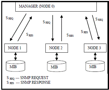
| In client server approach, a manager at node0 send SNMP request to all nodes i.e. (node1, node2 and node3) and get
SNMP response from them as shown in fig 1. Each manager node have to sent SNMP request to each node and
corresponding to this request managed node send SNMP response which leads to the inefficient utilization of
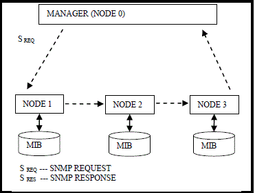
bandwidth and jamming in network traffic In case of mobile agent based network request-response does not passes through network links, mobile agent do these all
request-response operation locally at each node as shown in fig 2. In this network only Mobile agent with collected
information is passes trough network links. |
MATHEMATICAL FORMULAS FOR NM COST |
| Network management traffic i.e. (get_request & set_request) passes through system network have some cost
associated with it. This cost can be in term of bandwidth acquired for management data transfer or in term of time for
which network is not free size private use. Each model has different cost for network management traffic. It is one of
research topic that how to minimize the network management cost. The cost for network management does not only
depends on management data size but also depends on cost coefficient of network link through which management data
pass. To compare this cost there are some formulas here. |
| For C/S or Static Agent based network management model as shown in fig 1, cost of only one time polling all
network devices is would be computed as |
 |
| Equation 1 can be generalized for N number of nodes as shown in equation 4.2 |
 |
| Where K0,i : is cost coefficient of manager to managed node link, |
| Sreq : Size of SNMP request packet, |
| Sres : Size of SNMP response packet |
| If P is number of polling done for a time interval then cost for network management for that time interval would b
calculated as shown in equation 3 |
 |
| For Mobile Agent based Network management model cost of only one round trip is shown in equation 4.4, as the
request is not going from manager node to individual managed node every time & vice versa for response, MA traverse
the whole path and then send the response to manager node . |
 |
| But as MA do operation locally at managed node, so it may require carrying some partial results (δpr) to the next
node. In case of partial results the cost for mobile agent would be computed as shown in equation 5. |
 |
| In generalized form for N number of nodes the cost is computed for mobile agent is shown in equation 6. |
 |
| Where Ki,j : is cost coefficient of link between ith and jth, |
| SMA : Size of mobile agent , |
| δpr : Size of partial results information collected by MA from each node. |
| δpr is zero if MA agent performs like as a manager and does not carries any information from managed device for
further use. There is N+1 is number of network nodes and their index is starting from 0-N. If polling is done for a time
interval for network management then management cost for that interval would be computed as shown in equation 7 |
 |
| Where δd is some change in partial result as the number of times polling increases. |
| Thus from equation 3 and 7, we can observed that management cost in C/S Network management model is directly
proportional to number of request & response used to managed a device. But in MA based model it is directional
proportional to MA agent size as well as amount of partial result information collected from mobile agent. |
THEORETICAL CALCULATIONS FOR NM COST |
| For theoretical calculation of management cost for above two networks management models as shown in figs 1 & 2
and consider following parameters |
| SNMP request packet size = 50 byte, SNMP response packet size = 75 byte where is 50 byte is data information in
response packet, consider cost coefficient of all links between nodes i.e. (0-1,0-2,0-3 in fig 3 and 0-1, 1-2, 2-3, 3-0 in
fig 4 ) is 10, MA size is 1 KB. |
| Cc/s=K0,1*(Sreq+Sres)+K0,2*(Sreq+Sres)+K0,3*(Sreq+Sres)
=10*(50+75)+ 10*(50+75)+ 10*(50+75)
=3*10*125
=3750 Bytes |
| For MA which collect information |
| CMA=K0,1* SMA + K1,2 * (SMA + δpr ) + K2,3 * SMA + 2 * δpr) + K3,0 * (SMA + 3 *δpr)
=10*1024+10*(1024+50)+10*(1024+100)+10*(10 24+150)
=10*(1024+1074+1124+1174)
=43960 Byte |
| When the node is accessing the MIB data, p times there may be some small change in data i.e partial results data
information, so for multiple polling, cost of mobile agent is as: |
| For polling 5 times, we assume that only no change in the data. |
| CMA=K0,1*SMA+K1,2*(SMA+δpr+δd)+K2,3*(SMA (2*δpr)+δd)+K3,0*(SMA+(3*δpr)+δd)
CMA=10*1024+10*(1024+50+0)+10*(1024+100+0)+10*(1024+150+0)
=10*(1024+1074+1124+1174)
=43960 Byte |
| For polling 10 times, we assume that only 5 byte of data will be added at each node |
| CMA=K0,1*SMA+K1,2*(SMA+pr+δpr)+K2,3*(SMA+(2*pr)+δpr)+K3,0*(SMA+(3* pr)+δpr) |
| CMA=10*1024+10*(1024+50+5)+10*(1024+100+5)+10*(1024+150+5)
=10*(1024+1079+1129+1179)
=44110 Byte |
| For polling 50 times, we assume that only 15 byte of data will be added at each node |
| CMA=K0,1*SMA+K1,2*(SMA+δpr+δd)+K2,3*(SMA+(2*δpr)+δd)+K3,0*(SMA+(3* δpr)+δd) |
| CMA=10*1024+10*(1024+50+15)+10*(1024+100+15)+10*(1024+150+15)
=10*(1024+1089+1139+1189)
=44410 Byte |
| For polling 75 times, we assume that only 15 byte of data will be added at each node |
| CMA=K0,1*SMA+K1,2*(SMA+δpr+δd)+K2,3*(SMA+(2*δpr)+δd)+K3,0*(SMA+(3* δpr)+δd) |
| CMA=10*1024+10*(1024+50+15)+10*(1024+100+15)+10*(1024+150+15)
=10*(1024+1089+1139+1189)
=44410 Byte |
| For polling 100 times, we assume that only 20 byte of data will be added at each node |
| CMA=K0,1*SMA+K1,2*(SMA+δpr+δd)+K2,3*(SMA+(2*δpr)+δd)+K3,0*(SMA+(3* δpr)+δd) |
| CMA=10*1024+10*(1024+50+20)+10*(1024+100+20)+10*(1024+150+20)
=10*(1024+1094+1144+1194)
=44560 Byte |
| For polling 200 times, we assume that only 25 byte of data will be added at each node |
| CMA=K0,1*SMA+K1,2*(SMA+δpr+δd)+K2,3*(SMA+(2*δpr)+δd)+K3,0*(SMA+(3* δpr)+δd) |
| CMA=10*1024+10*(1024+50+25)+10*(1024+100+25)+10*(1024+150+25)
=10*(1024+1099+1149+1199)
=44710 Byte |
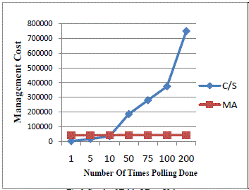
| Table 1 shows cost comparison between CC/S and CMA to access multiple rows of MIB table of managed device by
polling multiple times. |
| Fig 3 shows the graph of table 1 data values, which very clear represents that client server based model are good for
small network but as a network grows, there is rapid increase in the demand of bandwidth, whereas in mobile agent
based models they require high bandwidth for smaller network but shows better utilisation of bandwidth when the
network becomes large. |
| The table 1 shows cost only access for devices parameters by manager, if manager check these all parameters and
then again set their nominal value then it again required to sent set_request and get set_response for managed devices. |
| For managing each parameter in this way required to pass two pair of request and response through link between
manager and managed device in static manager as in fig 1 and if MA in fig 2 acts as a mobile manager then there is no
need to collect values of device parameters and they can be locally checked and set. In that case cost for management
activity of for singe table row is |
| Cc/s=K0,1*(Sreq+Sres)*2+K0,2*(Sreq+Sres)*2+K0,3*(Sreq+Sres)*2
=3*10*125*2
=7500 Bytes |
| For mobile manager value δpr is zero if managing activity is at managed node |
| CMA=K0,1*SMA+K1,2*(SMA+δpr)+K2,3*(SMA+2*δpr)+K3,0*(SMA+3*δpr)
=10*1024+10*(1024+0)+10*(1024+0)+10*(1024+0)
=10*(1024)*4
=40960 Byte |
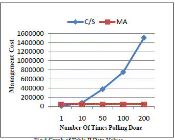
| The table 2 shows, cost comparison between CC/S and CMA to access managing multiple rows of MIB table of
managed device and fig 4 shows the corresponding graph. |
| The variation in management cost according to MA size is given in table 2 and fig 4 shows the graph which shows
management cost increases with increase in mobile agent size. |
INTRODUCTION TO WDM OPTICAL NETWORK |
| Optical communication is a form of data communication that uses light as the transmission medium. First-generation
optical networks simply replaced copper wires with optical fibers. Due to much lower attenuation and interference,
optical fiber has large advantages over copper wire in long-distance and high-demand applications. |
| New Open Distributed has offered network management a large set of solutions. For example worldwide TMN
manager/agent environment [12] provides a generalized framework for the management of telecommunication
networks. The centralized approach in this however entails drawback in scalability, reliability, efficiency and flexibility
is consequently unsuitable for large heterogeneous networks.[13][14] |
| The advantages of optical fiber are given below. |
| Numbers of optical signals at different carrier wavelengths are simultaneously carried by the same fibers. |
| The speed at which optical signals are communicated is far greater than the speed at which data can be processed
by electronic circuits. |
| Therefore, optical fiber is being used by many telecommunications companies to transmit telephone signals, Internet
communication, and cable television signals. |
| As of today, one single optical fiber can transport up to 320 Gbit/s and the capacity of more than 1Tbit/s is expected
within next few years. |
| In the near future, the emergence of new photonic technologies in the field of transport networks, such as WDM
(Wavelength-division Multiplexing) optical networks, will support a variety of services such as voice, audio, video and
Internet traffic. |
| The incredible growth of the bandwidth through one fiber, as well as future IP/WDM mesh networks, require the
implementation of some efficient mechanisms for the management of such networks, especially concerning reaction
speed in case of fiber break or component damage. |
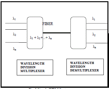
| Wavelength-division multiplexing (WDM) is a method to insert multiple channels or wavelengths over a single
optical fiber as shown in Fig 5. WDM maximizes the use of the installed fiber base and allows new services to be
quickly and easily provisioned over the existing fiber infrastructure. WDM offers bandwidth multiplication for carriers
over the same fiber pair. WDM alleviates unnecessary fiber build-out in congested conduits and provides a scalable
upgrade path for bandwidth needs. |
| Each message is assigned a different wavelength (frequency). Different wavelength lasers (called lambdas) transmit
multiple signals. The various signals carried on the fiber can be transmitted at a different rate from each other. |
| The current trend in the networking world is the development of a paradigm that enables the transport of IP traffic
over optical networks. Still, cost-effective transport solutions based on IP/WDM networks are attractive only if they
can deal with legacy systems like SDH/WDM or ATM/SDH/WDM. We must therefore consider that IP/WDM and
SDH/WDM need to co-exist on the same optical infrastructure in order to ensure efficient migration. Owing to the
inherent C/S nature of TMN environment the information flow between managers and agents increases. Consequently
the time for making decisions depending on human intervention becomes a critical issue. |
| The introduction of intelligent and mobile agents within optical networks should lead to the reduction of the
information flow through the management information channels and should moreover spare the usage of numerous
protocol stacks. Owing to this approach, optical networks will become more generic. They will be able to support the
future services requirements and as well as guarantee a fast reaction to the dynamic changes of traffic conditions.
Moreover the automatic reconfiguration should further reduce human intervention thereby reducing the risk of errors
and reaction time. |
SETTING UP OF OPTICAL CHANNELS IN AN OPTICAL TRANSPORT NETWORK |
| Optical Transport network (OTN) is another name for optical WDM network, which is currently being standardized
by the G.872 recommendation of ITU-T [15]. It is based on WDM technology, which allows multiplexing of several
wavelengths and leads to a tremendous increase in available bandwidth through one single optical fiber. |
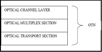
| OTN is defined by three sub-layers, which are the Optical Channel layer (OCH layer), the Optical Multiplexing
Section layer (OMS layer) and the Optical Transport Section layer (OTS layer) as shown in Fig 6. |
| OCH layer acts as a server layer on which any kind of rate-independent clients (e.g. IP, SDH, ATM) can initiate
connections between two nodes. A client is associated to one wavelength (or channel). The OCH layer contains a
wavelength routing function, while OMS layer is responsible for ensuring integrity of a group of wavelength
(wavelength multiplex) and the OTS layer is the interface between OMS and physical layer. |
| A physical device through which channels (also called λ - connections) are established for information flow in an
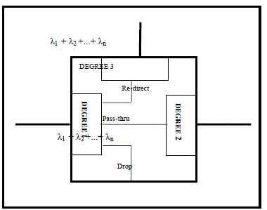
OTN network is called Add-Drop multiplexer. A variant of this, called Reconfigurable Optical Add-Drop multiplexer
(ROADM), is deployed across the OTN networks for long distance data transmissions. It can add, drop, pass or redirect
modulated light beams of various wavelengths in an optical fiber network as shown in Fig 7. |
| The direction from where the combined wavelengths can enter ROADM is called degree. A given ROADM can have
maximum 4 degrees. Each degree, shown in the Fig 3, consists of an optical amplifier unit and MUX/DEMUX unit for
wavelength management. |
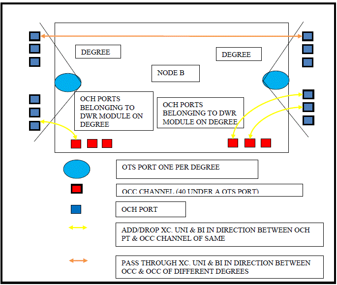
| The amplifier carries the OTS and OCC ports whereas OCH ports are present on client cards. As shown in Fig 8,
each OTS port has 40 OCC ports or channels in it. For putting client traffic from OCH ports to OTS port, optical cross
connects can be made only on degree basis. For example, in case of degree 1, only the OCH ports and OCC port
belonging to degree 1 could be cross connected. OCC ports are connected across the degrees by means of pass through
cross connects. |
LAMBDA- CONNECTIONS COST COMPUTATION FOR AN OPTICAL TRANSPORT NETWORK |
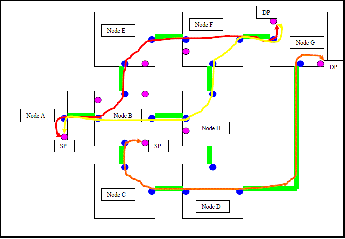
| Fig 9 shows a typical Mesh topology of ROADM nodes where three different (Red, Orange and Yellow) Optical
Channels are shown. Two are in between the Source Port (SP) of Nodes A and Destination Port (DP) of Node G and
one is between Node B and Node G. |
| Each of the blue circles is a degree on a given node. Node A is a single degree node, Node B is a 4 degree node, and
Node C is a two degree and so on. These degrees are numbered 1 to 4 in any manner. |
| Each degree consists of an optical amplifier unit and MUX/DEMUX hardware units. Amplifier card has OTS ports
(also called Network Ports) and MUX/DEMUX unit supports OCH ports (pink circle). |
| Each OTS port has 40 OCC ports or channels in it. As there are (max) 4 degrees, there are 4 OTS ports and a given
channel number, say 27, (OCC number 27) is present across all degrees. |
| For putting the client signal (traffic) from OCH ports to OTS port, optical cross connects can be made ONLY on
degree basis, i.e., say for degree 1, ONLY the OCH ports and OTS port belonging to degree 1 could be cross
connected. OTS ports are connected across the degrees by means of pass-through cross connects. |
| In order to create an optical connection through the OTN network from a given source port (OCH) to the destination
port, the availability of OCH, and OCC and OTS ports across the network is ascertained. In this work a mechanism is
being proposed that creates optical channels across the OTN network elements. |
PROPOSED MECHANISM FOR OCH, OCC AND OTS PORT AVAILABILITY |
| Finally, complete content and organizational editing before formatting. Please take note of the following items when
proofreading spelling and grammar: The user data or LAN connectivity is done on OCH port. |
| It can accept data up to 10Gbps. The user data can be put on to a given OCH port only if it is not a part of some other
optical channel. The network system needs to ensure it. From a given OCH port, the data is taken to OCC channel for
its entry into WDM domain. This can be done on degree basis. |
| A given OCH port and OCC port need to be part of the same degree. |
| All the OCC ports finally multiplex into an OTS port and thereafter the multiplexed signals travel together on a
single fiber. |
| The algorithm detail of the mechanism to check the availability of OCC & OCH port on source, destination and
intermediate NE is given below. |
| A manager, an agent and management applications interact with each other, as discussed in previous chapters, to
facilitate the channel creation in an automated manner across the OTN network. |
| Following are certain validations which a Manager runs on its end to ensure the channel creation. |
| VALIDATION |
| 1. Manager checks that destination port on source NE is in the same degree as source port and destination port is
of type OCC belonging to an OTS port. |
| 2. Manager checks that source port on destination NE is of type OCC belonging to an OTS port and on the same
degree as destination port on destination NE |
| 3. Manager checks source port and destination port for intermediate NE are of type OCC belonging to OTS port
and belong to same channel |
| Let Q is the total number of ROADM nodes present in an OTN network through which the channel creation has to
run |
| Algorithm CreateChannel() |
| { |
| 1. i=1; |
| 2. Path[Array]=NULL |
| 3. j=0 |
| 4. while(i<Q+1) |
| 5. Start While |
| 6. If (Destination OCC of Node[i] is free) |
| 7. Start If |
| 8. Make a cross - connection OCH-OCC (OCH to OCC) |
| 9. Path[j]= Node[i] |
| 10. j=j+1 |
| 11. End If |
| 12. Else |
| 13. Start Else |
| 14. Return Destination OCC is not free |
| 15. Exit |
| 16. End Else |
| 17. If (Node[i+1] is not the destination node) |
| 18. Start If |
| 19. If (Destination OCC on any degree is free) |
| 20. Start If |
| 21. Make a pass through connection OCC-OCC |
| 22. i=i+1 |
| 23. Path[j]=Node{i+1] |
| 24. j=j+1 |
| 25. Goto 17 |
| 26. End If |
| 27. Else |
| 28. Start Else |
| 29. Return OCC is not free |
| 30. i=i+1 |
| 31. Goto 17 |
| 32. End Else |
| 33. End If |
| 34. Else |
| 35. Start Else |
| 36. If (destination OCH is free) |
| 37. Start If |
| 38. Make a cross - connection OCC-OCH |
| 39. Path[j]=Node[i+1] |
| 40. End If |
| 41. End Else |
| 42. End While |
| 43. Show path array of Nodes |
| } |
| Each of network management models has its own impact on response time and network bandwidth utilization. In
client/server manager sends SNMP request to all nodes and get SNMP response from them. In-fact these requests
themselves involve transfer of data in the form of network management traffic passing through system network
incurring cost associated with it. This cost can be in term of bandwidth acquired for management data transfer or in
term of time for which network is not free. For Mobile Agent it is the size of agent class and the amount of information
which it will carry with it. |
COST COMPUTATION FOR CLIENT/SERVER MODEL |
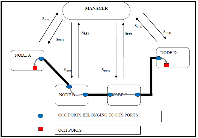
| As shown in Fig 6, a central manager sends the required SNMP requests to various nodes in the OTN network to
enquire about the availability of OCH, OCC and OTS ports. |
| Depending upon the required information, the algorithm explained above is run at the central manager and SNMP
requests for setting up needed cross-connects between the OCH ports and OCC ports are issues from the central
manager. |
| As discussed in earlier in the chapter, the management cost of client/server model in terms of no. of SNMP
request/response and link coefficient would be computed as shown in equation (8). |
 |
| A manager exchanges three requests/responses with an agent for setting up a cross-connect. Two requests are for
checking the availability of OCH and OCC ports and one for setting up the cross-connect. A more generic form of the
equation can be shown as expression (9) |
 |
| Where |
| K0, i : the cost coefficient of manager to managed node link, |
| Sres : the size of SNMP response packet |
| Sreq : the size of SNMP request packet |
| Multiplication by 3 is three pair of requests and response are generated each for, to check availability of OCC &
OCH port and to make connection between them respectively. |
COST COMPUTATION FOR MOBILE AGENT MODEL |
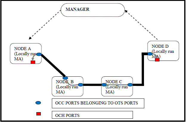
| In case of mobile agent, as shown in Fig 11, SNMP request & response do not pass through network links. Mobile
agent does all these request/response locally at each node. Mobile agents allow more and more of the network
management intelligence to move closer to the devices unlike the centralized model. |
| In this model mobile agent runs locally on every node to find out the availability of OCH & OCC ports and also to
make connection between them. |
| This saves the network management cost of request and response for each port and their connection, which is done
in client server model. |
| As discussed earlier, the management cost of MA-based model in terms of no. of SNMP request/response, size of
MA and link coefficient would be computed as shown in equation (10) |
 (10) (10) |
| As all operations are being performed locally by the MA and it doesn’t carry any additional information with it, the
overall cost would be computed as in equation (11) |
 (11) (11) |
| Where |
| K i,i +1 is cost coefficient of link |
| SMA is Size of Mobile Agent |
| Multiplication by 1 is that to enquire about free OCC & OCH port and to make connection between them is done
locally. |
COMPARISON BETWEEN CLIENT SERVER AND MOBILE AGENT MODEL |
| As discussed in earlier section, for theoretical quantitative evaluation of management cost for two network
management models let us assume the following: |
| SNMP request packet size (Sreq) = 50 Bytes, |
| SNMP response packet size in small network= 75 bytes |
| Sma (MA size) is 1 KB =1024 Bytes, |
| Data accessed by the task manager (Sres) in CS paradigm = β times of Sma |
| (Size of mobile agent << raw data collected in Client/Server model) |
| The management cost in terms of flow of management traffic around the management station in CS paradigm is computed as follows. |
| Ccs= (Sreq+Sres) = 50 + β * Sma |
| Client Server cost computation |
| CC/S = ����,��
����
=�� * ( Sreq + Sres) * 3
= K0,1 * (Sreq + Sres) * 3 + K1,2 * (Sreq + Sres) * 3 + K2,3 * (Sreq + Sres) * 3 + K3,0 * (Sreq + Sres) * 3
= 10 * (50 +75) * 3 * 4
= 15000 |
| Client server cost computation with raw data of 15 times of SNMP response |
| CC/S = ����,��
����
=�� * (Sreq + Sres) * 3
= K0,1 * (Sreq + Sres * 15) * 3 + K1,2* ( Sreq + Sres * 15) * 3 + K2,3 * (Sreq + Sres *15) * 3 + K3,0 *
(Sreq + Sres * 15) * 3
= 10 * (50 + 75*15) * 3 * 4
= 141000 |
| For large networks SNMP response is β times of Sma, Take β = 2 |
| CC/S = ����,��
����
=�� * (Sreq + Sres) * 3
= K0,1 * (50 + 2 * 1024) * 3 + K1,2 * (50 + 2 * 1024) * 3 + K2,3 * (50 + 2* 1024) * 3 + K3,0* (50 + 2 *
1024) * 3
= 10 * (50 + 1024*2) * 3 * 4
= 251760 |
| Mobile agent cost computation |
| CMA = ����,��+��
����
=�� * SMA * 1
= K0,1 * SMA * 1 + K1,2 * SMA *1 + K2,3 * SMA *1+ K3,4* SMA *1+ K4,0* SMA*1
= 10 * 1024 * 1 * 4
= 40960 |
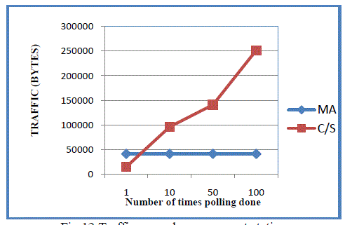
| Based on the computation shown, the cost of traffic around management station is tabulated in Table 3 and shown in
Fig 12. |
| It may be noted from Table 3 that with the increase in number of polling, the management cost of C/S increases
many fold as compared to MA model as also illustrated in Fig 12. |
CONCLUSION |
| Now a day’s optical transmission gives a solution for tremendous increase of application and transfer of data over
one node to other in an efficient manner. But in large network client server approach has various disadvantages which
led the mobile agents to overcome the problem of client server and the flexibility increases efficiently. |
| In this chapter we shows the experimental results for client server and MA which shows client/server are better for
small network and mobile agent are good for large network. An algorithm is proposed to find out the availability of
OCH, OCC, & OTS port in optical network scenario and compare the theoretical results for both client server and
mobile agent approach. |
| |
Tables at a glance |
|
|
| |
Figures at a glance |
 |
 |
 |
 |
 |
| Figure 1 |
Figure 2 |
Figure 3 |
Figure 4 |
Figure 5 |
|
 |
 |
 |
 |
 |
| Figure 6 |
Figure 7 |
Figure 8 |
Figure 9 |
Figure 10 |
|
 |
 |
| Figure 11 |
Figure 12 |
|
| |
References |
- Subramanian, M., Network Management Principles and Practice, Addison Wesley, 2000.
- W. Stallings. SNMP, SNMPv2 and CMIP: The practical guide to network management standards. Addison-wesley publication, 1994.
- Tripathi, A., Ahmed, T., Pathak, S., “Paradigms for Mobile Agent Based Active Monitoring Of Network Systems”, IEEE, 2002.
- Shamila Makki, Subbarao Wunnava, Next Generation Networks and Code Mobility. ISAST Transactions on Communications and Networking, No.1 Vol. 2, 2008.
- S. Vinoski, “CORBA: Integrating Diverse Applications Within Distribute Heterogeneous Environments”, IEEE Communications Magazine, Vol. 35, No. 2, 1997.
- Liotta, G. Knight, and G. Pavlou, “Modeling Network and System Monitoring Over the Internet with Mobile Agents”, IEEE, 1998.
- T. Magedanz, K. Rothermel, and S. Krause, “Intelligent Agents: An Emerging Technology for Next Generation Telecommunications”, INFOCOM ’96, pp.24-28, 1996.
- D. Raz, B. Shavitt, “An Active Network Approach for Efficient Network Management”, Proceedings of the 1st International Working Conference on Active Networks (IWAN’99), LNCS Vol. 1653, pp. 220-231, 1999.
- J. E. White, “Telescript Technology: The Foundation for the Electronic Marketplace”,General Magic White Paper, 1994.
- Joy et. al., “The Java Language Specification”, 2nd ed. Reading, MA: Addison Wesley, 2000.
- Acharya, M. Ranganathan, and J. Saltz, “Dynamic linking for mobile programs, In Mobile Object Systems: Towards the Programmable Internet”, pp. 245-262, Springer-Verlag, 1997.
- ITU M.3100 “Principles for a Telecommunications management network” May 96
- Dialong Zhang, Werner Zorn, “Developing network management applications in an application-oriented way using mobile agent”, Computer Networks and ISDN systems 30 (1998) 1551-1557
- Daneil Rossier- Rammuz and Rudolf Scheurer “An Introduction to Optical Agents: Intelligent and Mobile Agents for WDM Optical Network Management” Springer US 2002 Online ISSN 978-0-387-35491-0
- ITU G.872, “Architecture of Optical Transport Networks”, Pre Published version, April 1999.
|