ISSN ONLINE(2278-8875) PRINT (2320-3765)
ISSN ONLINE(2278-8875) PRINT (2320-3765)
A.Ilakkia1 and R.Rajalakshmi2
|
| Related article at Pubmed, Scholar Google |
Visit for more related articles at International Journal of Advanced Research in Electrical, Electronics and Instrumentation Engineering
This project investigates the reduction of Total Harmonic Distortion (THD) by SAPF using Selective Harmonic Elimination (SHE) through instantaneous reactive current theory (id-iq method). The SAPF also called as ‘harmonic isolator’ is used for compensating the harmonics, for providing reactive power and for balancing asymmetrical loads. Instantaneous reactive current theory (id-iq method) is used to produce conductance command for SAPF. The voltage loop is operated by proportional integral (PI) controller. This control method provides reduced THD and the improvement of fundamental component. SHE method is used to eliminate the lower order harmonics, in this work harmonic of order 7 and 13 are eliminated, thus reducing the THD. This work is carried out by using the MATLAB 7.13 software
Keywords |
| Shunt Active Power Filter (SAPF), Voltage Source Inverter (VSI), Total Harmonic Distortion (THD), Selective Harmonic Elimination (SHE), id-iq method |
INTRODUCTION |
| The increasing use of power semiconductor switching devices in power supply, computers and other microprocessor based equipment causes harmonics in the electrical system. Such harmonics may cause serious problems like excessive heating of motors and malfunction of sensitive electronic equipments. These harmonics can be filtered by using either active or passive power filters [1].In comparison with passive filters, SAPF have been proposed as an acceptable alternative because of its capability to compensate randomly varying currents, to eliminate the harmonic currents generated by nonlinear loads, to improve power factor and for reactive power compensation [4]. The various types of non linear loads are adjustable-speed drives, electronic ballasts, switch mode power supply (SMPS), and uninterruptible power supply (UPS). Various control methods and strategies like id - iq method, p-q theory, unity power factor method, etc., [2] were put into effect for minimizing the harmonics in the electrical network. |
| In case of power installations, the current harmonics are of most concern because, the harmonics originates as currents causing several ill effects [3]. Since the range, types and number of units of equipments causing harmonics have been raised nowadays, their side effects should be considered very carefully. The harmonic currents causes several problems like overloading of neutrals, overheating of transformers, annoyance tripping of circuit breakers, over-stress of power factor and skin effect. The problems caused by harmonic voltages are voltage distortion, and zero-crossing noise. To pare down the above problems the SAPF is used. The id - iq method provides good result for the loads in both balanced and unbalanced conditions. SHE is used to eliminate the low order harmonics thus improving the efficiency [5]. |
SYSTEM DESCRIPTION |
| SHUNT APF |
| Filter is classified into two types viz. i) Active filter and ii) Passive filter. Active filter is further classified into: i) SAPF, ii) Series APF and iii) Hybrid APF. A SAPF consists of a controllable voltage or current source. The voltage source inverter (VSI) based SAPF is the most common type of filter used today, due to its well known topology and ease of installation. The configuration of a VSI based shunt APF is shown in Fig. 1. It consists of a DC-bus capacitor (C), power electronic switches and interfacing inductors (L). SAPF acts as a current source, compensating the harmonic currents due to nonlinear loads. The operation of SAPF is based on injection of compensation current (If) which is equivalent to the distorted current (IH), thus the original distorted current is eliminated. The equation of the SAPF is written as, |
| Is + If = IL (2.1) |
| The load current (IL) consists of both the fundamental component and the harmonic component (IH), hence the equation is written as, |
| Is + If = IL+ IH (2.2) |
| As the injected compensating current (If) cancels the harmonic current (IH), then the equation is written as, |
| Is = IL (2.3) |
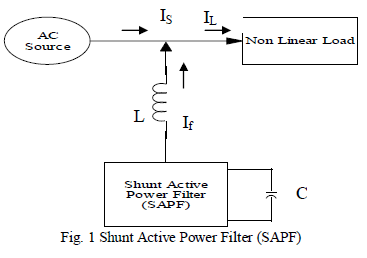 |
| Thus the resulting source current contains only the fundamental component of the nonlinear load and is free from harmonics. In view from the nonlinear load, the SAPF is regarded as varying shunt impedance. For harmonic frequencies, the impedance is either zero or small but for the fundamental frequency it is infinite. |
| SELECTIVE HARMONIC ELIMINATION (SHE) |
| SHE method is used to eliminate low order harmonics up to the order of 13 thus minimizing the THD of the output waveform. In this work harmonics of the order 7 and 13 are eliminated. SHE method requires low switching frequency to reduce the semiconductor losses and to minimize the harmonic distortion. In this technique, the switching angles are calculated such that low order, up to (a-1) harmonics are eliminated, where ‘a’ is the number of switching angles. For an m level inverter a= (m-1)/2. The switching angles must be less than 90°. If the angles are greater than 90°, then it leads to improper signals. Higher order harmonics are filtered using additional filters between the inverter and the load. The most significant low-frequency harmonics are chosen for elimination by proper selection of angles among different level inverters and the amplitude of the fundamental component is adjusted. The output voltage waveform is obtained by using Fourier series and solved either by nonlinear transcendental equations or Newton-Raphson method. |
INSTANTANEOUS ACTIVE AND REACTIVE CURRENT COMPONENT (id-iq) METHOD |
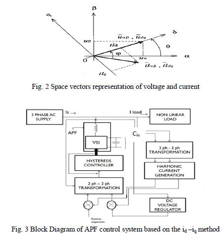
| In id-iq method, the reference currents are generated through the instantaneous active and reactive current component of the nonlinear load. Thus the three phase current component a-b-c will be transformed into α-β-0 components in stationary frames and based on the Park transformation it is rotated by an angle θ in synchronous reference frame. The DC bus capacitor regulating DC voltage and the generation of the error signal for switching purpose by PI controller are the control schemes used. Under balanced voltage condition, the response of instantaneous reactive power theory (p-q theory) and id-iq theory are identical. But during distorted voltage condition, this id-iq method is predominant to instantaneous reactive power method. From the instantaneous active and reactive current components ild and ilq of the nonlinear load, the active filter current is obtained. By using Park and Clarke transformation, the α-β component are fed to vector rotation where it will be rotated over an angle θ to follow the frame d-q and hence the d-q component is obtained. The voltage across the mains and the distorted currents in α-β components are calculated in the same way as that of p-q theory. The load currents of the d-q components obtained from the Park transformation is given by, |
 |
| Under balanced, sinusoidal voltage condition, θ is a uniformly increasing function of time and is sensible to harmonics and unbalanced voltages. The space vector representation of voltage and currents in α-β coordinates is shown in Fig. 2. The block diagram of APF control system based on the id –iq method is shown in Fig. 3. |
 |
| A.DC VOLTAGE REGULATOR |
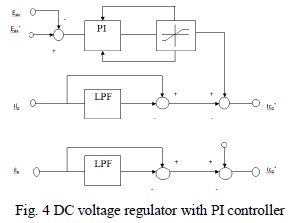 |
| The circuit of DC voltage regulator with PI controller is shown in Fig. 4. A DC voltage regulator generates a fixed output voltage of a preset magnitude which remains constant regardless of the changes in the input voltage or load conditions. The regulator converts the dc input voltage to a switched voltage applied to a power MOSFET or BJT switch. The filtered power switch output voltage is fed back to a circuit that controls the power switch either on or off so that the output voltage remains constant regardless of the change in input voltage or load current. The voltage regulation on the converter DC side will be performed by a proportional-integral (PI) controller. The capacitor voltage error C* dc - Cdc is given as the input to the PI controller. By controlling the first positive sequence id1h + harmonic of the active current, the active power flow in VSI with the capacitor voltage Cdc will be controlled. Similarly the flow of reactive power is controlled by the regulation of first harmonic quadrature current of positive sequence iq1h + . On the contrary the primary end of the SAPF is free from harmonics and hence the current iqlh + is always set to zero. |
| B.CONTROL STRATEGY |
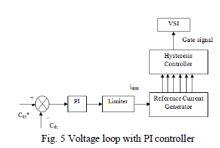 |
| In the feedback mechanism shown in Fig. 5, the PI controller is used to calculate an error value as the difference between a measured process variable and a desired set point. The control scheme comprises of PI controller, limiter and reference current generator. The capacitor voltage will be compared with a set reference value and the peak value of the reference current is obtained. The peak current (Imax), the output of the PI controller is found and it is multiplied by the unit sine vectors in phase with the individual source voltages to obtain the reference compensating currents viz. Isa *, Isb *, Isc *.These reference currents and the actual currents (Isa, Isb, Isc) are equated at a hysteresis controller, which delivers the error signal to put on the converter switches. The DC link capacitor voltage is always maintained constant during the operation of the converter. In this control scheme, each phase of the converter is measured independently. The lower switch of the converter is put on to increase the current of a particular phase, while the upper switch of the corresponding converter is put on to decrease the current of a particular phase. Hence the potential of PI controller is sustained. |
SIMULATION AND RESULTS |
 |
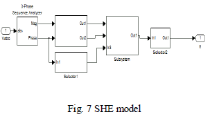 |
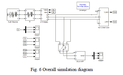
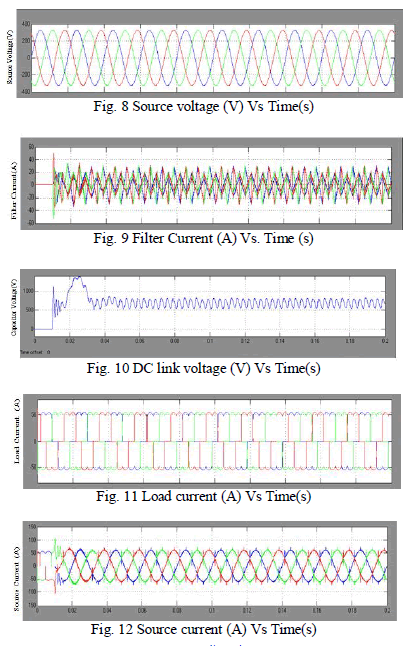
| The overall simulation model of the system is shown in Fig. 6 and Fig. 7. The output responses of the voltages and current of the system is shown in Fig. 8 – Fig. 12. |
 |
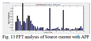
| The FFT analysis of the system using APF with reduced THD is shown in the Fig. 13. |
 |
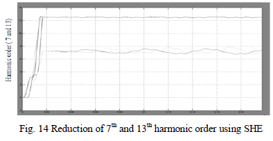
| The output response of the system with reduced harmonics at the order of 7 and 13 using SHE is shown in Fig. 14. |
 |
CONCLUSION |
| This paper presents a work with Selective Harmonic Elimination method by SAPF through instantaneous active and reactive current component id -iq method. In id-iq method angle θ can be calculated directly from the voltage mains and thus makes this method to be frequency independent. Thus synchronization problems with un-balanced voltages can be avoided. The id -iq control method allows the operation of the SAPF in variable frequency conditions without adjustment. The id -iq method provides good efficiency when compared with instantaneous reactive power theory. Various soft computing techniques can be used for obtaining more accurate results, better harmonic reduction and fast response. |
References |
|