ISSN ONLINE(2278-8875) PRINT (2320-3765)
ISSN ONLINE(2278-8875) PRINT (2320-3765)
Sonia Sunny1, Rajesh K2
|
| Related article at Pubmed, Scholar Google |
Visit for more related articles at International Journal of Advanced Research in Electrical, Electronics and Instrumentation Engineering
This paper proposes an improved topology of an isolated DC-DC converter fed sensorless BLDC drive. The main aim is to control the input voltage of the inverter by changing the duty ratio of switches in the converter for controlling the speed of the motor. In this paper, a comparison study with controlled voltage source fed sensorless BLDC drive is also done and its disadvantages presented .The proposed method finds maximum application in battery powered electric vehicles, aircrafts etc. The isolated DC-DC converter results in less size and weight and also provides isolation by means of High Frequency Transformer (HFT). The BLDC drive employs Direct Back-EMF Detection technique for the sensorless control of the motor. The power circuit simulation for the isolated DC-DC converter fed drive, being high frequency, is done in PSIM and the control circuit simulations are done in MATLAB. Later, both MATLAB and PSIM are coupled by SimCoupler to obtain the speed and torque waveforms.
Keywords |
| BLDC, sensorless, back-emf detection, isolated DC-DC converter, HFT |
INTRODUCTION |
| BLDC motors, also known as Permanent Magnet DC Synchronous motors, are used in a great amount in industrial sectors demanding safer control applications of industrial drives. The demand for highly efficient and low cost drives led to the application of BLDC motors in a wide variety of commercial and household applications, such as refrigerators, washing machines, personal computers, to military and automotive industry extending to aerospace. |
| The control of BLDC motors can be done in either sensor or sensorless mode, but to reduce overall cost of actuating devices, sensorless techniques are employed. In sensor control, Hall sensors are used for position sensing. In sensorless control either use back-emf of motor for position sensing or use motor parameters for position estimation. In this paper direct back-emf sensing is used [1]-[2]. Other methods include flux linkage technique [3]-[4], back-emf integration, freewheeling diode conduction technique. The direct back-emf detection method is relatively simple requires only back -emf zero crossing points of the three phases but possess inherent lower speed range. Since only two phases are energized at a time for a BLDC motor, the floating third phase provides the back-emf necessary for forming the commutation sequence for the three phase inverter of the motor. |
| A more useful control approach lies in separating the speed control and inverter commutation. The regulation of dc link input voltage of the inverter controls the speed. The main focus of this paper lies in the control of dc link voltage of sensorless BLDC drive fed from an isolated DC-DC converter. The converter used here is dc-dc full bridge converter due to its advantageous topology [5].The proposed circuit simulation is done in PSIM and MATLAB. The power circuit simulation is done in PSIM and the control circuit of the sensorless drive in MATLAB is later coupled. Only the dc-dc converter is working at high switching frequency, the inverter switches are working at low frequency. Furthermore, direct control of DC link voltage with controlled voltage is also presented and compared and its disadvantages are stated. |
OVERVIEW OF THE DRIVE |
| The BLDC Model |
| Normally BLDC drive is energised from an ac supply through rectifier, DC link and inverter. Only two phases are energised a time for a BLDC motor. In this paper, a DC-DC isolated full bridge converter is inserted in the DC link to control the dc voltage. |
| A BLDC motor has a permanent magnet rotor and concentrated windings on the stator. The three phase inverter switches are six step commutated with conducting period of 120 ° for each phase, the third phase is floating. For sensorless working, the zero-crossing point of the induced back-emf is needed. This point is obtained from the terminal voltage of the motor. This point is actually the point where the rotor pole crosses a phase on the stator. We need a low pass filter to filter off the unwanted voltages and noise. Since a LPF provides phase delay, which is utilized for commutation of switches so that phase currents are in phase with flat portion of back-emf. |
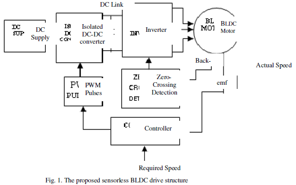 |
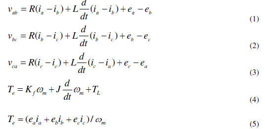
| The block diagram of the proposed drive is shown in fig.1. The mathematical modelling includes the basic equations |
 |
 |
| The Inverter |
| The three phase inverter uses six step commutation strategy with each switch on for a period of 120 áôü .Only two phases are energized at a time leaving the third phase floating. The isolated converter switches are only working at high switching frequency (in kHz) while the inverter switches are working at low frequency(in Hz).The method of controlling the BLDC motor is 2π/3 angle switch on method being implemented in the inverter. The commutation strategy is implemented by detecting the zero crossing points of the phase back-emfs. |
| The Isolated full bridge DC-DC Converter |
| Even though it is a variation of buck converter topology, this converter has got many advantages compared to other isolated DC-DC converters. Here there is no chance of flux walking. Also, for the same output voltage and power rating the switches need to carry only half of the current than in half-bridge isolated converter. The high frequency transformer (HFT) provides electrical isolation between input and output which is the added advantage compared to other DC-DC converters. The high frequency operation demands need for low power loss core design initiating the use of ferrite core. The duty cycle of the full bridge converter is given by |
 |
| Where vout, vin the output and input voltages and N2, N1 the number of turns of primary and secondary of the transformer and D is the duty ratio. |
| For the BLDC motor to be driven at a specified speed lesser than the rated speed we need to change the duty ratio of the inverter switches or dc-dc converter switches by applying PWM signals. But PWM signals to inverter switches cause commutation delay and high switching losses especially at high speeds and at sudden speed changes. So, it is better to control the DC link voltage leaving the inverter switches only for commutation. Here in this proposed method we are changing PWM duty ratio of the switches in the isolated DC-DC converter for varying the DC link voltage. The turns ratio of the transformer also affects the output voltage. Apart from the low size of filter circuits needed, due to high switching frequency, harmonic control is also easy. The isolation assures safe operation of the drive. This method finds maximum application in battery powered vehicles, aircraft, missiles, aerospace etc. |
BLDC DRIVE CONTROL THEORY |
| The proposed BLDC drive works in sensorless mode detecting the zero crossing points of phase back-emfs thus enabling 120° conduction mode for the inverter switches. The back-emf method helps to know the initial rotor position. Since back- emf developed in the starting stage is less, due to less speed, we can’t use the sensorless control strategy using back-emf at the start. Instead we have to start the motor in open loop. |
| The commutation algorithm is obtained by detecting the zero crossing points(ZCPs) of the back-emfs. A switching pulse is produced for the respective phase, 30º after its zero crossing point detection, and the switch is kept ON for 2π/3 interval. If low to high transition takes place at the ZCP ,the corresponding upper switch of that phase is triggered and vice-versa. Likewise the conduction pattern changes every π/3 angle, indicating six switching modes in a full cycle. This method is known as 2π/3 Angle Switch-on Mode. |
| The speed control of the sensorless BLDC drive can be done in either of the following ways. |
| Vary the duty ratio of the switches in the isolated DC-DC Converter |
| The required speed and actual speed difference is calculated and the speed error is minimized using a PI controller. The output of controller decides the control voltage needed for the PWM switching of isolated DC-DC converter switches. The control voltage is compared with a high frequency carrier (which is also the switching frequency of the converter switches) and the duty ratio of the converter switches is varied. So by using this method a variable output voltage is obtained in the DC link. An additional advantage is that the turns ratio of the converter also helps in modulating the DC link voltage. |
| Using a controlled voltage source as input to the inverter |
| The required speed and actual speed difference is calculated the speed error is fed to a PI controller whose output determines the voltage required from the source. A controlled voltage source typically an op-amp circuit is used. |
SIMULATION AND RESULTS |
| The proposed isolated DC-DC converter fed sensorless BLDC drive is simulated using both MATLAB and PSIM softwares. Here the power circuit is done in PSIM and the control circuit in MATLAB. The control signal generated in MATLAB varies the duty ratio of the isolated DC-DC converter switches. The isolated DC-DC converter is designed in PSIM and the PSIM power circuit provides the phase voltages to sensorless BLDC motor modelled in MATLAB via Simcoupler. |
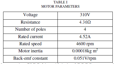
| Table I shows the parameters of the BLDC motor chosen for simulation. |
 |
| First simulation is done for sensorless BLDC drive with isolated DC-DC converter for a speed of 1000 rpm. The power circuit model in PSIM is shown in fig.2. |
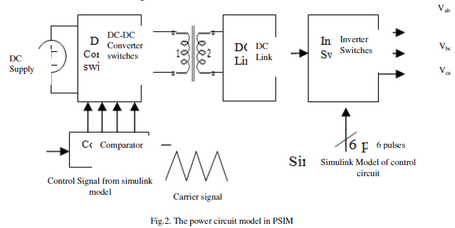 |
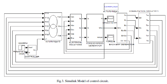
| The output from PSIM model consists of three pulses vab, vbc, vca which are given to the MATLAB simulink model of sensorless controlled BLDC drive. The simulink model is shown in fig.3. |
 |
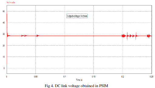
| The simulation waveform for the output voltage obtained in PSIM for the speed of 1000 rpm(less than rated) is shown below in Fig.4. The output voltage is only nearly 30V required for 1000rpm.This is also the DC link voltage of the sensorless BLDC drive. |
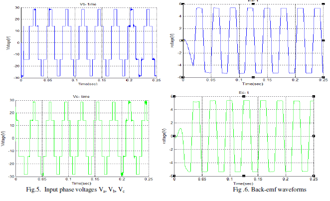
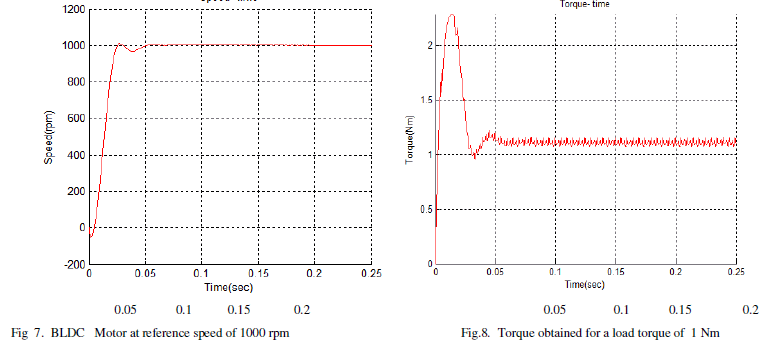
| The input phase voltages, back-emf, speed and torque waveforms are shown in Fig.5, 6, 7 and 8 respectively for the BLDC motor running at 1000 rpm. The voltage waveforms are 120º phase shifted from each other. The load torque applied is only 1Nm. |
 |
 |
 |
 |
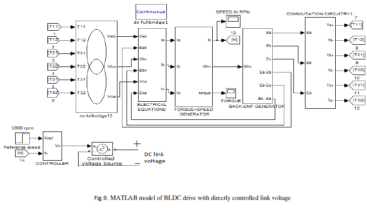
| The MATLAB simulink model of controlled voltage source fed BLDC motor is shown in fig.9. |
 |
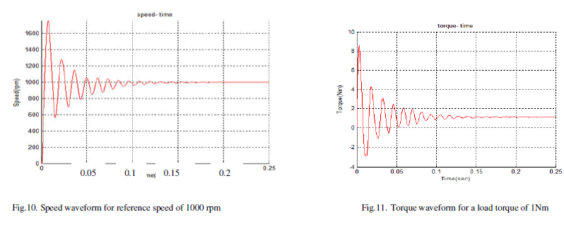
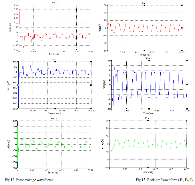
| The simulation waveforms obtained for controlled voltage fed sensorless BLDC drive are shown in Fig. 10, 11 ,12and 13 respectively. Fig.10 shows the speed waveform for a refernce speed of 1000 rpm. The torque waveform is similar to speed waveform consisting of initial overshoots and oscillations. The waveform shown in Fig.11. is for a load torque of 1 Nm. The input phase voltages in Fig.12 are 120 degree phase shifted and are stepped waveforms. |
 |
 |
| The simulaton results show that it is better to have speed control by varying duty ratio of the isolated DC-DC converter switches rather than contolling the DC link voltage directly by voltage controlled source. Two important output measurements of a motor are speed and torque .Here the motor control is done for a speed of 1000 rpm and a load torque of 1 Nm. Even after being sensorless both these waveforms attain steady state stability in no time of 0.05 sec (Fig 7 and Fig 8) for isolated DC-DC converter fed motor. For the directly controlled DC link voltage fed drive it takes 0.15 sec (Fig.10 and Fig.11).Thus a difference of 100ms comes into play which is very significant at start-up of a motor/drive. Overshoots and oscillations are also there in the latter before stabilizing which hinders smooth operation of the drive. |
| This is because in the former speed control is done by commutating switches in the converter only leaving inverter switches only for phase commutation. But in the latter inverter has to perform both these functions leaving the drive a bit ambiguous at the start. Therefore Isolated DC-DC Converter fed sensorless BLDC drive prove to be a good replacement where size and time are critical parameters. |
CONCLUSION |
| The simulation results obtained using the proposed BLDC drive system have proved the simplicity of the application of isolated DC-DC converter in the DC link for sensorless speed control. The implemented back -EMF sensing method along with isolated DC-DC converter has superior performance and provided much wider motor speed range being readily stable. |
| The major advantage lies in the separation of inverter commutation from speed control part which implements clean and smooth operation of the drive avoiding PWM switching of inverter switches. Only the converter switches need to operate at the high switching frequency. Harmonics control is easy due to high switching frequency. The HFT provides isolation ensuring safe operation of the drive at the expense of reduced size and weight mandatory for aircrafts, battery powered electric vehicles etc. |
| The disadvantage is that the HFT requires careful design especially selection of core and also cost is higher. |
References |
|