International Journal of Advanced Research in Electrical, Electronics and Instrumentation Engineering
ISSN ONLINE(2278-8875) PRINT (2320-3765)
ISSN ONLINE(2278-8875) PRINT (2320-3765)
J. Adeline Sneha1, K. Kumar2, V. Bens Joie Victor3, J. Aran Glenn4
|
| Related article at Pubmed, Scholar Google |
Visit for more related articles at International Journal of Advanced Research in Electrical, Electronics and Instrumentation Engineering
This paper proposes the controlling of Induction motor drives.Because of low maintenance and robustness, induction motors have many applications in industries. Speed control of induction motor is more important to achieve maximum torque and efficiency. Various control techniques such as scalar control, vector control, Sensor-less control are used. These Schemes suffers from parameter sensitivity and limited performance at low speed of operation. Sensor-less control of induction motor drive using model reference adaptive system with PI controller as reference model will limit the performance at low speed of operation. In this thesis, a novel adaptation mechanism is proposed which replaces PI controller in MRAS adaptation mechanism by a fuzzy logic controller. This is applied to a vector controlled drive and experimentally verified. This makes the reference model free from pure integration and less sensitive to stator resistance variations. This improves the performance of MRAS based sensor-less drives at low speed of operation.
Keywords |
| Induction Motor, Sensor less, Fuzzy Logic Control, Low Speed, Speed Control |
INTRODUCTION |
| Nowadays, AC motors, in particular squirrel cage induction type, are widely used in industry due to their simple and rugged structure. Moreover, they are economical and immune to heavy overloads. However the use of induction motors also has its disadvantages, mainly the controllability, due to its complex mathematical model and its nonlinear behavior during saturation effect. Induction motor (IM) require complex control algorithms, because there is no linear relationship between the stator current and either the torque or the flux. This means that it is difficult to control the speed or the torque. So the development of high performance motor drives to control such motor is very important in industrial applications, high performance control and estimation techniques for induction motor drives are very fascinating and challenging subjects and recently many techniques have been developed for induction motor drives and hence very good control performances have been achieved. Generally, a high performance drive system must have good dynamic speed command tracking and load regulating responses, and the performances are insensitive to the drive and load parameter variations. Among the existing techniques, the most commonly used is the proportional-integral (PI) controller. The PI controller is very easy to be implemented, but the PI controller cannot lead to good tracking and regulating performance simultaneously. Moreover, its control performances are sensitive to the system parameter variation and load disturbances. Recently the modern controls, such as optimal control, variable structure System control, adaptive control, etc., have been applied to yield better performance. However, the desired drive specifications still cannot be perfectly satisfied by these methods. |
| In many motor control applications, direct control of torque is highly desirable as a system with a fast response to changes in torque is very beneficial. The field oriented control (FOC) or vector control theory is the base of a special control method for induction motor drives. With this control method, induction motors can successfully replace expensive dc motors. The invention of vector or field-oriented control, and the demonstration that ac motor can be controlled like a separately excited dc motor, brought renaissance in the high performance control of induction motor drives. In fact, with vector control, induction motor drive outperforms the dc drive because of higher transient current capability, increased speed range and lower rotor inertia. |
| The most important aspect of the field-oriented control of induction motor is the transformation of the stator currents into a torque producing component (the quadrate q) and a flux-producing component (the direct path d). To enable the flux producing current component to align with the rotor magnetic flux, the accurate estimation of a transformation parameter called the unit vector is required. However, if this unit vector can be correctly determined, then the ac drive performance will depend on the effectiveness in producing the appropriate torque command. Sensor less control deals Motor control without speed or position sensors. Such technique measures stator current and voltages. The advantage of such a control is less maintenance, no cable to machine transducers, no electrical noise. |
PROBLEM STSATEMENT |
FUNDAMENTAL BASIS-FLUX LINKAGE |
| Sensor-less control of IM can use fundamental model-based estimation methods, which in their simpler forms typically work well above about 2% of base speed. These fundamental model-based methods usually describe the machine by d – q axis equations, where sinusoidal distribution around the air gap is assumed. As this neglects space harmonics, slotting effects, etc., it is termed a fundamental model. Fundamental models have an inherent limit. As the stator frequency approaches zero rotor-induced voltage goes to zero, and the IM becomes unobservable .Methods are either implemented in open-loop or as closed-loop observers (estimators), making use of the error between measured and estimated quantities to improve their behavior. |
| Operation at very low speed and continuously at zero may need SI techniques for position estimation. These methods utilize asymmetric properties, either the saliency of the rotor. The simplest form for the stator voltage equation using the usual symbols would be |
 |
PERMANENT MAGNET SENSING USING MOTIONAL EMF |
| Practical difficulties in the use of motional EMF sensing occur since the windings carry rapidly changing currents, giving substantial inductive effects. Since the EMF is zero at zero speed, a finite speed threshold must operate. A particular problem in an Synchronous Machine such as the Permanent Magnet machine is that starting is also position dependant, so rotor position and magnetic field polarity are ideally required to avoid a starting transient which may be in reverse. Special arrangements, perhaps an open-loop ramp, may be made for starting with parameters chosen to suit drive and load. |
| Simple motional EMF sensing schemes have limitations: |
| 1) Sensing is not possible at low speeds |
| 2) Filtering and phase shift gives a limited dynamic range |
| 3) Upper limit on the useful speed range when assumed rapid decay of switched off current no longer happens |
| 4) Phase EMF measured, for a star connection an extra lead is needed. |
| The third-harmonic component of the EMF waveform of trapezoidal PM machine can be used, reducing the phase shifting problem with the basic scheme and making operation possible at higher speeds. |
PERMANENT MAGNET SENSING USING INDUCTANCE VARIATION |
| Where inductance is a function of rotor position, then position can be deduced from winding current and its rate of change. This applies even at stand-still where motional EMF is zero. There are problems: with surface-mounted magnets, inductance variation with position is only from magnetic saturation; at higher peed motional EMF dominates; inductance variation has two cycles per electrical cycle of the PMM, giving a sensed position ambiguity. |
MODEL REFERENCE ADAPTIVE SYSTEM |
| The main logic behind MRAS scheme is that there is a reference model and an adaptive model where in the reference model is used to determine the required states and the adaptive model also known as adjustable model provides the estimated values of the states. The error obtained between the reference and adaptive model is given to an adaptation mechanism which adjusts the adaptive model by generating the estimated value of rotor speed. The process of adjusting the adaptive model is made to continue till the error obtained between the two models tends to zero. The basic model reference adaptation scheme is given in the fig 2.2 |
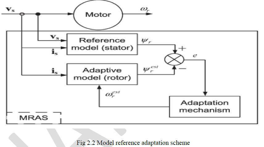 |
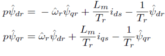
| The adaptive model usually describes the rotor equation and the rotor flux components are expressed in terms of rotor speed and stator current. The following equations give the rotor flux components as obtained from the adaptive model. |
 |
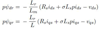
| The reference model is usually expressed by the voltage model representing the stator equations. The reference model gives the following equations for reference rotor flux components. |
 |
FUZZY LOGIC |
CONTROLLED MRAS OBSERVER |
| Fuzzy logic is especially advantageous for problems that cannot be easily represented by mathematical modeling because data is either unavailable, incomplete or the process is too complex. Such systems can be easily upgraded by adding new rules to improve performance or add new features. In the conventional methods of MRAS speed observer PI controller was commonly used in the adaptation mechanism which is generating estimated speed which in turn is reducing the speed tuning signal error. |
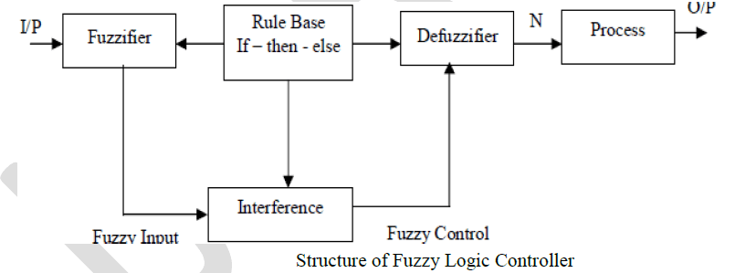
| The structure of a fuzzy logic controller is as shown in Fig. 2.3. The input is given to the fuzzifier where the fuzzyfication of the input takes. In the fuzzyfication component block scale mapping of input data and selection of fuzzyfication functions are to be considered. Scale mapping of data is nothing but converting the range of input variables which can be understood by the fuzzy logic controller where a specific range will be given. The fuzzyfication process converts the crisp data into fuzzy set. The rule base block actually holds the fuzzy rules which are applied to the given input. The decision making logic is present in the interference part which will make the decision as per the rules and logic present. Mostly the Mamdani’s method is used for decision making. It uses AND or minimum operator as fuzzy implication operator. The other method used in decision is Takagi and Sugeno (TS) fuzzy model. The defuzzifier block converts the fuzzy output after the decision making and processing is done in the interference into non-fuzzy output which can be given to the process or plant where the control is required. |
 |
MEMBERSHIP FUNCTIONS |
| In the last article, the rule matrix was introduced and used. The next logical question is how to apply the rules. This leads into the next concept, the membership function. The membership function is a graphical representation of the magnitude of participation of each input. It associates a weighting with each of the inputs that are processed, define functional overlap between inputs, and ultimately determines an output response. The rules use the input membership values as weighting factors to determine their influence on the fuzzy output sets of the final output conclusion. Once the functions are inferred, scaled, and combined, they are defuzzified into a crisp output which drives the system. There are different membership functions associated with each input and output response. Some features to note are: |
| SHAPE - triangular is common, but bell, trapezoidal, have sine and, exponential have been used. More complex functions are possible but require greater computing overhead to implement. HEIGHT or magnitude (usually normalized to 1) WIDTH (of the base of function), SHOULDERING (locks height at maximum if an outer function. Shouldered functions evaluate as 1.0 past their center) CENTER points (center of the member function shape) OVERLAP (N&Z, Z&P, typically about 50% of width but can be less). Fig.3.3 illustrates the features of the triangular membership function which is used in this example because of its mathematical simplicity. Other shapes can be used but the triangular shape lends itself to this illustration. The degree of membership (DOM) is determined by plugging the selected input parameter (error or error-dot) into the horizontal axis and projecting vertically to the upper boundary of the membership function(s). |
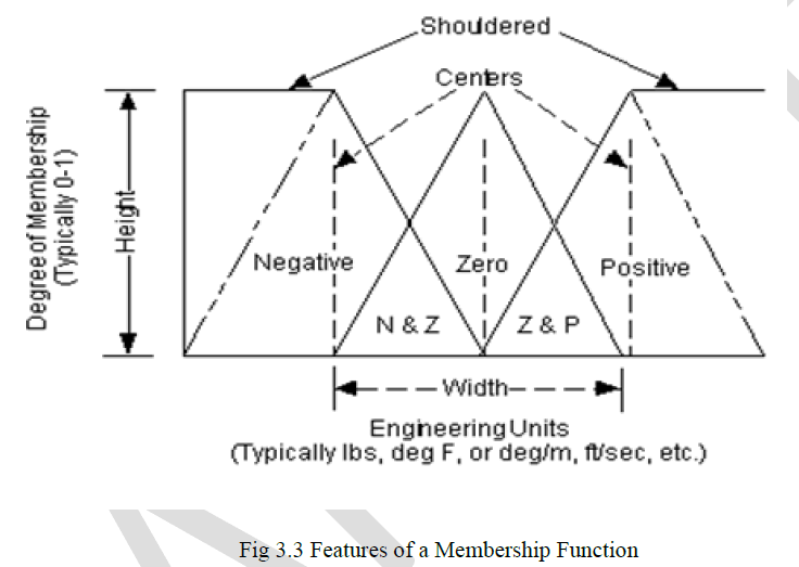 |
| In Fig.3.3 consider an "error" of -1.0 and an "error-dot" of +2.5. These particular input conditions indicate that the feedback has exceeded the command and is still increasing. |
ERROR-DOT FUNCTION MEMBERSHIP |
| The degree of membership for an "error" of -1.0 projects up to the middle of the overlapping part of the "negative" and "zero" function so the result is "negative" membership = 0.5 and "zero" membership = 0.5. Only rules associated with "negative" & "zero" error will actually apply to the output response. This selects only the left and middle columns of the rule matrix. For an "error-dot" of +2.5, a "zero" and "positive" membership of 0.5 is indicated. This selects the middle and bottom rows of the rule matrix. By overlaying the two regions of the rule matrix, it can be seen that only the rules in the 2- by-2 square in the lower left corner (rules 4, 5, 7, 8) of the rules matrix will generate non-zero output conclusions. The others have a zero weighting due to the logical AND in the rules. |
CONCLUSION |
| In this Thesis, the performance of MRAS based induction motor drive controlled is studied and presented by using Fuzzy logic controller. The main advantage of fuzzy control is that when the reference speed changes the control parameters need not to be changed but this is not the case with conventional PI controller. The speed estimation of motor using PI controller deteriorates at low speeds and hence proposed a FLC based speed estimation to replace conventional PI controller. Simulation results have been and it was found that FLC shows better transient performance Even though the performance of the motor has improved by using FLC but at very low speeds near to zero speed the control of motor is still a challenge and will be addressed in future. |
References |
|