ISSN ONLINE(2278-8875) PRINT (2320-3765)
ISSN ONLINE(2278-8875) PRINT (2320-3765)
V. Thirumurugan1, Dinu Paul 2
|
| Related article at Pubmed, Scholar Google |
Visit for more related articles at International Journal of Advanced Research in Electrical, Electronics and Instrumentation Engineering
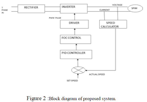
It is usual find single-phase induction motor (SPIM) in several house, office, shopping, farm, and industry uses,which are become each time more refined and requiring variable speed drives. In view of the low cost of this machine, the recognition of sensorless speed control is themore reasonable option for SPIM drives. This paper presents a tender for sensorless variable speed SPIM drive based on direct rotor field orientation techniques. An spectator based on two independent linear close-loop control systems provides the assessment of the rotor flux and speed from the measurements of the stator currents and voltages. These estimates are used by close-loop system forspeed control and flux regulation in order togovern the voltages to be applied in the main and auxiliary windings by a three-leg VSI inverter. None variable transformation is used in this tender in order to eliminate the asymmetry of the stator windings of the SPIM. The performance of the proposed sensorless speed control is satisfactorily verified from computer simulations.
Keywords |
| Sensorless, , Single-Phase Induction Motor Drives, Direct Rotor Field Orientation. |
INTRODUCTION |
| Traditionally used in fractional and sub-fractional horse power applications, the single-phase induction motor (SPIM)is usually found in several dynasty, office, shopping, farm, and industry appliances such as air conditioning systems, mixers,washers, blowers, compressors, fans, vacuum cleaners, pumps, etc. A SPIM is basically an unbalanced electric machine established by a squirrel-cage rotor and with different impedances. When the machine is fed by a single phase power source, the main winding produces a pulsating and stationary magnetic field, while the auxiliary winding, usually connected with a series capacitor, emulates a second phase to obtain the start-up torque for the SPIM. Although the auxiliary winding is often disconnected by a centrifugal switch when the SPIM rotor reaches 60% to 80% of rated speed, itcan be maintained at running operation in order to provide a higher and less effervescent torque. Many proposals to improvethe SPIM performance are based in the use of an electronicallyswitched series capacitor in the auxiliary winding, which canbe controlled to improve the machine performance at different operating conditions.The development of more erudite applications and the introduction of low-cost static power converters have stimulated the development of variable speed drives for SPIM. |
| The most of the control techniques for the SPIM drive arebased on the use of constant V IF relation or on vectorial control with field orientation, usually employingproper variable transformations in order to disregard the symmetry of the stator winding.Sensorless techniques is the more reasonable option for the control of fractional and low cost SPIM applications, since the small size and low cost of this motor does not corroborate the use of speed sensors due to reductionof reliability and increase of complexity, cost, difficulties, weight, size, and electrical susceptibility. Some approaches have been suggested for sensorless control of SPIM drives,where the rotor speed estimation are usually obtained from the machine model and the measurements of stator voltages and currents.This paper presents a scheme for sensorless variable speed SPIM drive based on direct rotor field orientation techniques. |
| An observer based on two autonomous linear close-loopcontrol systems provides the estimations of the rotor flux from the measurements of the stator currents and voltages, consentinga better rotor flux regulation which is decoupled of the torque control. From these rotor flux observers, the rotor speed is estimated. These estimatives are used by close-loop systemsfor speed control and flux regulation in order to determine the voltages to be applied in the main and auxiliary windings by a three-legs VSI inverter. None variable transformation is used in this proposal in order to eliminate the unevenness of the stator windings of the SPIM. The presentation of the proposed sensorless speed control is satisfactorily demonstrated from computer simulations |
FIELD ORIENTATED CONTROL |
| Field oriented control methods control the frequency,amplitude and phase of the motor drive voltage vector that is generate by the stator currents. Field Orientated Control (FOC) expedites the inductionmotor to be controlled in a method similar to a DCmotor. A simple control such as the V/Hz strategy has limitations on the performance. |
| To achieve improved dynamic performance, a more multifaceted control scheme needs to be functional, to control the induction motor. With the mathematical dispensation power offered by the microcontrollers, implement advanced control strategies, which use arithmetic transformations in order to decouple the torque production and the magnetization functions in an AC induction machine. Such decoupled torque and magnetization control is commonly called rotor flux oriented control, or simply Field Oriented Control (FOC) |
THE MAIN PHILOSOPHY BEHIND THE FOC |
| In order to understand the spirit of the Field Oriented Control technique, let us begin with an overview of the separately excited direct current (DC) Motor. In this type of motor, the excitation for the stator and rotor is individualistically controlled. An electrical study of the DC motor shows that the produced torque and the flux can be independently tuned. The strength of the field excitation (the magnitude of the field excitation current) sets the value of the flux. |
| The current through the rotor windings determines how much torque is produced. The commutates on the rotor plays anstimulating part in the torque production. The commutates in contact with the brushes, and the mechanical assembly is designed to switch into the circuit the windings that are mechanically affiliated to produce the maximum torque. This arrangement then implies that the torque formation of the machine is convincingly near most favorable all the time. The key point is that the windings are succeeded to keep the flux formed by the rotor windings orthogonal to the stator field. Induction machines do not have the same key facial appearance as the DC motor. |
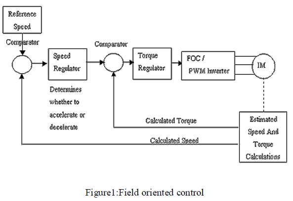 |
| This arrangement then means that the torque production of the machine is equitably near optimal all the time The windings are managed to keep the flux produced by the rotor windings orthogonal to the stator field. The goal of the FOC (also called vector control) on synchronous and asynchronous machine is to be able to distinctively control the torque producing and magnetizing flux components. Vector control accordingly generates a three-phase PWM motor voltage output derived from a complex voltage vector to control a complex current vector derived from motor's stator current input through projections or rotations back and forth between the single -phase speed and time dependent system and these vectors 'rotating reference-frame two-coordinate time invariant system. |
| Such complex stator motor current space vector can be defined in a (d,q) coordinate system with orthogonal components along d (direct) and q (quadrature) axes such that field flux linkage component of current is aligned along the d axis and torque component of current is aligned along the q axis. The induction motor's (d,q) coordinate system can be superimposed to the motor's instantaneous (a,b,c) three-phasesinusoidal system Components of the (d,q) system.current vector, permit conventional control such as proportional and integral, or PID, control, as with a DC motor. |
| Projections associated with the (d,q) coordinate system typically involve |
| Forward projection from instantaneous currents to (a,b,c) complex stator current space vector illustration of the three phase sinusoidal system. |
| Forward three-to-two phase, (a,b,c)-to-( , ) |
| Vector control implementations usually assume ungrounded motor with balanced three-phase currents such that only two motor current phases need to be sensed. Also, backward two-to-three phase, ( , )-to-(a,b,c) projection uses space vector PWM modulaton. |
| However, it is not exceptional for sources to use three-to-two, (a,b,c)-to-(d,q) and inverse projections. |
| Decoupled torque and field currents can thus be derived from raw stator current inputs for control algorithm development. |
| Whereas magnetic field and torque components in DC motors can be operated relatively simply by separately controlling the respective field and armature currents, inexpensive control of AC motors in variable speed application has required development of microprocessor-based control. Inverters can be implemented as either openloop sensorless or closed-loop FOC, the key restriction of open-loop operation being mimimum speed possible at 100% torque, namely, about 0.8 Hz compared to standstill for closed-loop operation. |
| There are two vector control methods, direct or feedback vector control (DFOC) and indirect or feedforwardvector control (IFOC), IFOC being more commonly used because in closed-loop mode such drives more easily operate throughout the speed range from zero speed to high-speed field-weakening. In DFOC, flux amount and angle feedback signals are directly calculate using so-called voltage or current models. In IFOC, flux space angle feedforward and flux magnitude signals first measure stator currents and rotor speed for then deriving flux space angle proper by summing the rotor angle corresponding to the rotor speed and the calculated reference value of slip angle corresponding to the slip frequency. Sensorless control of AC drives is effiencient for cost and reliability considerations. Sensorless control requires derivation of rotor speed information from considered stator voltage and currents in combination with open-loop estimators or closed-loop observers. |
WHY FIELD ORIENTED CONTROL |
| Asynchronous machines have some natural restrictions with a V/Hz control attitude. FOC control bypasses these restrictions by decoupling the effect of the torque and the magnetizing flux. With thedecoupled control of the magnetization, the torque-producing factor of the stator flux can now be consideration of as independent torque control. Decoupled control, in low speeds, the magnetization can be maintained at the suitable level, and the torque can be proscribed to regulate the speed. The processing ability provided by the microcontrollers enables the mathematical transformations to be carried out very promptly. This in turn implies that the entire algorithm directing the motor can be executed at a fast rate, enabling higher vigorous performance. In addition to the decoupling, a dynamic replica of the motor is now used for the calculation of many quantities such as rotor flux angle and rotor speed. This means that their power is accounted for, and the overall quality of control is enhanced. |
SENSORLESS CONTROL |
| Consequently, this has opened a new attractive area for research and during the last few years a variety of different solutions has reached the market. Neural networks, artificial intelligence and sensorless. Controlled induction motor drives without mechanical speed sensors at the motor shaft have the attractions of low cost and high consistency. To replace the sensor the information on the rotor speed is obtained from measured stator voltages and currents at the motor terminals. Vector-controlled drives involve estimating the magnitude and orientation of the fundamental magnetic flux waves in the stator or in the rotor. Open-loop estimators or closed-loop observers are used for this purpose. They differ with respect to accurateness, robustness, and sensitivity against model parameter variations. Dynamic behaviour and steady-state speed accuracy in the low-speed range can be achieved by exploit sponging effects of the machine. |
 |
SIMULATION DIAGRAM |
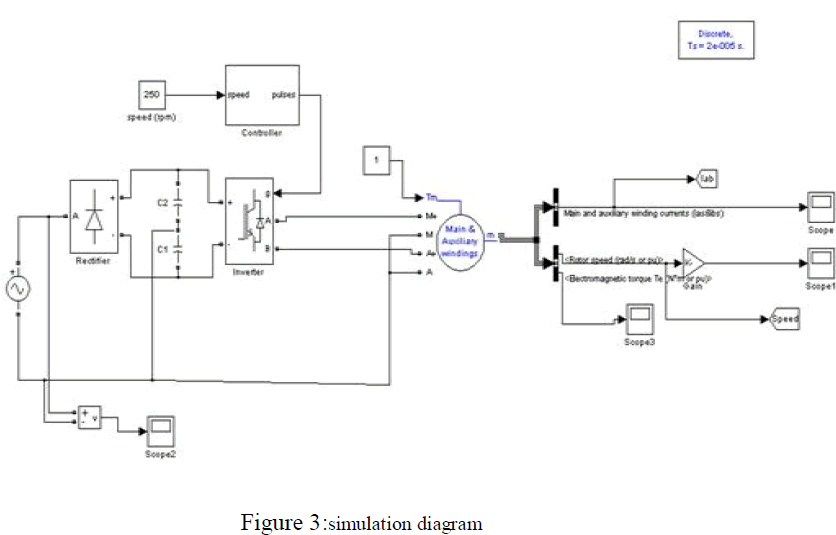
| Three phase supply is converted into DC by the converter. Then, the DC is converted in to AC by inverter. The inverter MOSFETS switching pulses are controlled through pic controller. Pic controller gets speed and frequency feedback from induction motor and it produces pulses to switch on inverter MOSFETs in time. Based on this pulses inverter output varies to maintain V/f constant. By this method speed control of single phase induction motor is controlled by V/F method effectively. thesubsytem unit converts the measured current and voltages to corresponding analog values and which in turn given to PWM inverter. |
 |
SIMULATION RESULTS |
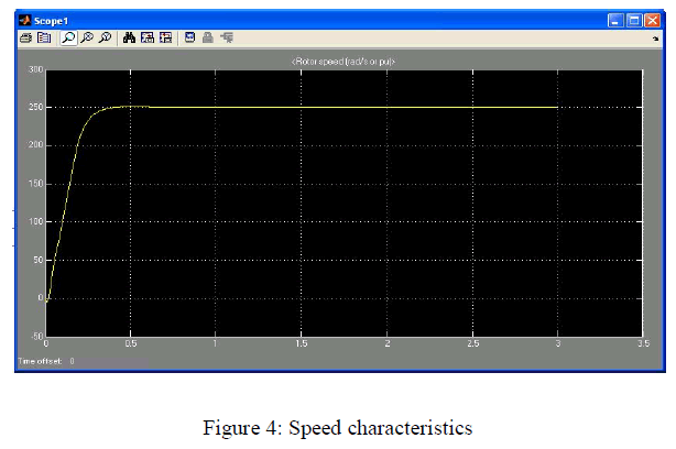
| The proposed sensorlesssystem for variable speed drive for SPIM is shown in Fig 3, and its performance in speed and flux control is proved from computational simulations .the SPIM is started with half load and accelerated to 250 rpm. After .5 s, the speed develops machine is accelerated again to 250 rpm. The proposed observer estimates accurately the rotor speed, and the speed control offerings a good performance since Wrfollows the reference with an error smallest than 3%. The amplitude of the rotor flux Ar is practically maintained constant by the flux control system. The corresponding speed characteristics is shown in figure 4, the speed is zero initially and which develops the given speed after sometime. |
 |
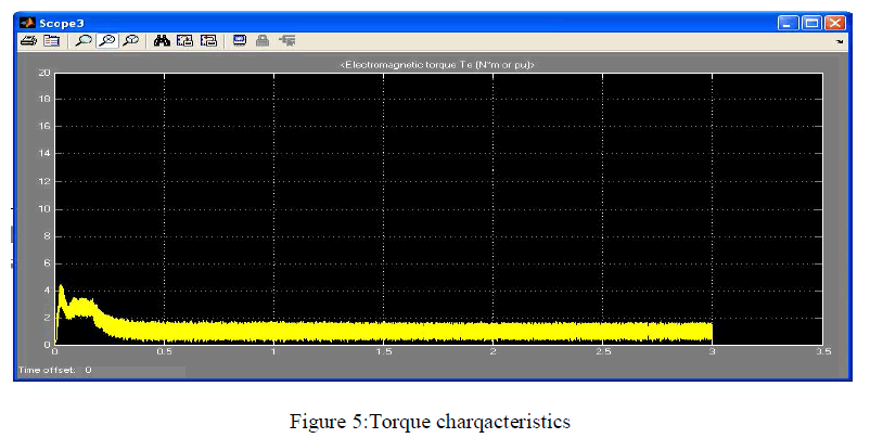
| The torque is zero initialy after it develops required torque about 4N/m and Finally settles to a low value . The torque characteristics are shown in figure 5.The speed regulation and torque characteristics of the system is improved a lot compared to the sensored speed control scheme.Also the main and auxiliary winding currents are improved. |
 |
CONCLUSION |
| Speed controlled induction motor drives are wide-spread electromechanical systems appropriate for a large range of industrial applications. When high dynamic performance and high exactitude control in a wide speed range are required, induction motor vector control based on the accessibility of the speed sensor is used. However, the speed sensor reduces the robustness and dependability of the IM drive and increases its cost. Hence, for medium and low performance applications, sensorless control of induction motor is becoming an industrial customary. In recent years, a large variety of different solutions has been applied in profitable products; at the same time, the problem of IM sensorless control has been greatly treated in technical literature, becoming an gorgeous assignment for different nonlinear control techniques.This project presents a proposal for sensorless variable speed SPIM drive based on direct rotor field orientation techuiques. |
| An observer based on two independent linear close-loop control systems provides the assessment of the rotor flux and speed from the measurements of the stator currents and voltages. The stator voltages and currents are measured with the help of current and potential transformers. These estimatives are used by close-loop systems for speed control and flux regulation in order to decide the voltages to be applied in the main and auxiliary windings by a three-legs of VSI inverter. Pic microcontroller is used as an embedded controller. Thus the speedcontrol is obtained without the help of any type of sensors. The performance of the proposed sensorless speed control is satisfactorily demonstrated from computer simulations. |
References |
|