ISSN ONLINE(2278-8875) PRINT (2320-3765)
ISSN ONLINE(2278-8875) PRINT (2320-3765)
M.Meera1, Dr.M.Muruganandam2
|
| Related article at Pubmed, Scholar Google |
Visit for more related articles at International Journal of Advanced Research in Electrical, Electronics and Instrumentation Engineering
This paper proposes a plug-in electric vehicle battery charger using SEPIC converter with coupled inductor. Here, the charger operates as a switched mode power supply (SMPS). The output dc voltage is controlled by varying the duty ratio of dc/dc converter by PWM technique. In addition, a new approach is introduced to control the dc link voltage using PI and PID controllers. The proposed model provides reduced cost, lower switching losses, lower conduction losses and higher efficiency. This topology optimize the efficiency of the converter over the battery voltage range (9V - 38V) and load conditions without adding any additional circuit or implementing any on/off control techniques. The configuration without full bridge LLC converter are presented and analyzed. A 3.3 KW Lithium-ion battery with an output voltage of 9V to 38V from variable dc link voltage is simulated. In comparison to conventional approaches, the efficiency of the SEPIC converter is improved by 6%.
Keywords |
| SEPIC converter, coupled inductor, Duty ratio, PI and PID controller. |
INTRODUCTION |
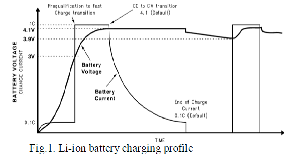
| Among various plug-in electric vehicle battery technologies Lithium-ion battery has dominated the battery market. This is because of its attractive features like high energy density, no memory effect and slow loss of charge.It is a secondary type of battery. The Li-ion battery charging profile is depicted in Fig.1. The voltage of a deeply depleted Liion battery can go down to 1V according to this profile. A wide voltage range of the on-board charger is mapped to a wide voltage range of Li-ion cell. |
 |
| SEPIC is a type of dc/dc converter that iscommonly utilized in the power factor correction. Since it allows the output voltage to be greater than, less than or equal to its input voltage. The output voltage of the SEPIC converter is controlled by the duty cycle of the control transistor and it provides non-inverted output voltage. SEPIC is similar to the buck-boost converter. But it has an advantage over the buck-boost converter that is the low input current harmonic can be achieved by the proper selection of the inductor in the SEPIC converter [1]. |
| Normal ac-dc rectifiers followed by the bulky capacitors suffered from high input harmonic content, which does not meet the international standards and diminishes the power factor at the mains. This is done by connecting DC-DC converter at the end of the rectifier which presents a control technique totrack the input voltage by the input current. This can be achieved by various dc/dc converters like buck, boost, buck-boost, CUK and SEPIC. Among these converters boost is mainly used for power factor correction since it possess low input current distortion. However it possesses a great drawback that is the input voltage is smaller than the output voltage. This difficulty is overcome by using SEPIC converter [2]. |
| According to the requirements of the battery board system that is fixed into the battery pack, current-controlled or voltage-controlled charge modes are actuated. The ac current is absorbed at unity power factor with no harmonic distortion with respect to the earlier integrated charger [4]. |
| Charger systems are classified into off-board and on-board types with unidirectional or bidirectional power flow. Unidirectional charging limits the requirement of hardware’s and simplifies the interconnection issues while bidirectional charging supports the battery energy injection back to the grid. Typical on-board charger limits power because of weight, space, and cost constraints. They can be incorporated with the electric drive to avoid these troubles. The availability of charging infrastructure reduces on-board energy storage requirements and costs. An off-board charger can be designed for high charging rates and it is less constrained by size and weight [3]. |
| Single Ended Primary Inductance Converter (SEPIC) at the DC-end of a single-phase diode bridge rectifier operating at the discontinuous conduction mode (DCM) is a good alternative to the conventional buck or boost converter, where a low input current harmonic content is obtained with proper inductor selection of the converter [5- 14]. |
| Battery charger that can act in response to the condition of a battery, which modifies the battery charging actions compare to the battery algorithm, is known as a smart charger. On the contrary, a standard or simple battery charger delivers a pulsed dc or constant dc power source to a battery to be charged. The charge on the battery and its output depends on time which does not vary in a simple charger. For that reason, smart chargers are chosen for NEV battery charging application [15-18]. |
CONVENTIONAL SYSTEM |
| In the existing system, a typical plug-in electric vehicle charger circuit consisting of two power converters, with first-stage for ac input power rectification and power factor correction and second-stage for voltage regulation and galvanic isolation using dc/dc converter. In the first-stage, a SEPIC converter is used for the power factor correction. Using SEPIC converter the dc link voltage can be varied over a wide battery voltage range without satisfying the compatibility with universal grid input voltage. |
| In second stage, zero-voltage switching (ZVS) topologies are used which will reduce the turn-on and turn-off losses. But the problem associated with this topology is that the switches should be operated at high switching frequency. If the switches are operated at this high switching frequency, then the switching losses will increases which in turn reduce the efficiency of the entire converter topology. Hence the design and construction of the converter becomes difficult [19-20]. |
 |
| The schematic of a conventional battery charger based on SEPIC PFC and full bridge LLC topologies is plotted in Fig.2. |
| This paper proposes a new approach to improve the efficiency over full battery voltage range (9V-38V) by eliminating the LLC topology thereby reducing the circulating current and switching losses which occurs due to the zero-voltage switching technique. Here the transformer is replaced by the coupled inductor which will act similar to the transformer by providing galvanic isolation as well as it reduces the cost and losses that is associated with the transformer. This makes the overall circuit very simple and cost-effective. SEPIC is also used to improve the battery performance without disturbing the volume of charger and also provides the constant output voltage when input voltages are low or high. |
| In addition to the above modifications, PI controller is used in the proposed system. This controller will control the output to the input relation. The error between actual and reference voltage is checked by the proportional controller. This error is compensated by comparing the error with the repeated sequence thereby improving the efficiency of the entire converter [21-25]. |
PROPOSED SYSTEM |
A. Block diagram |
| The block diagram of the proposed system based on SEPIC converter in a closed loop system is shown in Fig.3. The coupled inductor in the SEPIC converter will reduce the ripple, limits the inductance requirements and also provides galvanic isolation by preventing the excess current entering into the battery if occurs will reduces the lifetime of the battery. The output voltage loop reference of SEPIC PFC stage is obtained from the battery voltage and this output is forced to follow the variation of the battery voltage. The increase in state of charge will gradually increases the reference voltage. |
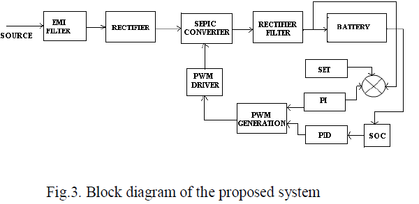 |
| The closed loop of the proposed system consists of state of charge and voltage control loop. According to the battery charge condition, the battery is operated either at CC (constant current) or CV (constant voltage) mode. Based upon the above mentioned modes either the reference voltage or reference current is generated. This generated reference voltage or reference current is compared with the actual voltage or actual current obtained from the output of the converter. This in turn generates the duty ratio at which the switch is needed to be turned on. The duty ratio is compared with the repeating sequence and a PWM wave is generated. |
| In the voltage control loop, the actual voltage is compared with the constant voltage and the error generated is processed through the PI controller. The output of the PI controller is compared with the output of the SOC control loop. This in turn is compared with the repeating sequence. Thus the pulse width is further reduced, which will increases the efficiency of the entire converter system. Hence, the duty ratio of the switch is adjusted and the switches are turned-on/turned-off regarding to the generated PWM signals. |
B. Operating principle of Proposed system |
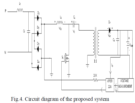
| Fig.4. shows the circuit diagram of the proposed system, consisting of inter-coupled SEPIC converter. The miniaturization of charger is essential for using it in portable electronic apparatus. This can be achieved by using SEPIC converter. Like other switched-mode power supplies, the SEPIC exchanges the energy between the capacitors and inductors in order to convert the voltage. The amount of energy exchanged is controlled by switch S1, which is typically a transistor such as a MOSFET since it offers high input impedance and does not require biasing resistors as it is controlled by differences in voltage rather than a current. |
| SEPIC converter consists of two inductors and a capacitor which is also known as flying capacitor. SEPIC will regulate the unregulated input supply and also improves the efficiency. Coupled inductor is used to reduce the on-board space and provides isolation. During charging condition, the capacitor acts as a load and stores energy. During discharging condition, the output voltage produced is related to the rate of change of current and not to the original charging voltage thus allowing different input and output voltage. |
 |
C. Modes of operation |
| This section reveals the operating principles of the SEPIC converter based SMPS for battery charger. The power flow direction of each mode is analyzed in the following section. The proposed system consists of two modes of operation. The operating modes are described as follows. |
| Mode I: |
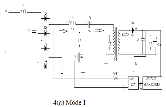 |
| During this mode, switch Q1 is turned on. The inductor L1 gets charged by VL1 and the capacitor gets charged by Vc. The current-flow path is depicted in Fig. 4(a). Output capacitor C0 provides its energy to the battery. Depending upon the charge in the battery the pulses given to the switch is varied by setting the required duty ratio. |
| Mode II: |
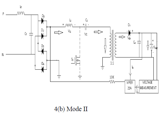 |
| During this mode, switch gets Q1 is turned off. The inductor L1 discharges through the coupled inductor. The current-flow path is depicted in Fig. 4(b). Here the gate pulses given to the switch is stopped. Thus the battery gets charged by the energy that is transferred in the couped inductor. |
D. Charging methods of Li-ion battery |
| There are two modes by which the battery is charged that is the constant current mode (CCM) and constant voltage mode (CVM). This mode of operation requires a dual control loop, which will control both the output voltage of the converter through an outer loop control and its input through an inner loop control. In this paper the developed charger will be verified through CCM/CVM charge by the experiments along with their control algorithm [25-29]. |
| The characteristics of Li-ion battery are shown in the fig.5. The discharge voltage of Li-ion battery is 3.0V and after reaching full charge the maximum voltage will be 4.1V-4.2V. Initially the battery is charged by constant current mode (CCM). When the voltage of the battery reaches full voltage, then it starts to operate in the constant voltage mode (CVM). In CCM the battery ischarged at a rate between 0.5- 1C, as soon the battery reaches its maximum voltage the mode shifts to CVM, the charger current decreases exponentially whereas the voltage remains constantly. |
 |
E. State of charge (SOC) algorithm |
| A State of charge algorithm is used to identify the SOC of the battery pack. In the pre-charging mode and constant current charging mode, the current control mode is activated. SOC algorithm will generate different reference current to regulate the charging current to be 0.1C and 1C, respectively. According to the SOC algorithm the duty ratio is calculated and also determines whether the battery should be operated in constant current control mode or constant voltage control mode. This algorithm will also provide the reference value for current or voltage (Iref or Vref) which is then compared with actual value and provides specified duty ratio. Based upon this duty ratio a PWM pulse is generated and this is compared with PWM pulse generated by comparing the constant voltage and the actual output voltage. This type of comparison will improve the lifetime of a battery when compared to theconventional plug-in electric vehicle battery charger technique. |
| This type of power supply is similar to the switched mode power supply (SMPS) which is useful for battery chargers where the output is mainly based on constant current control mode. For the accurate voltage regulation it is convenient to operate the Li-ion batteries in both modes that is in constant current and constant voltage. The charging operation will becompleted as soon as the charging current degrades to 0.02 C and the charger is disabled. |
F. Simulation and its results |
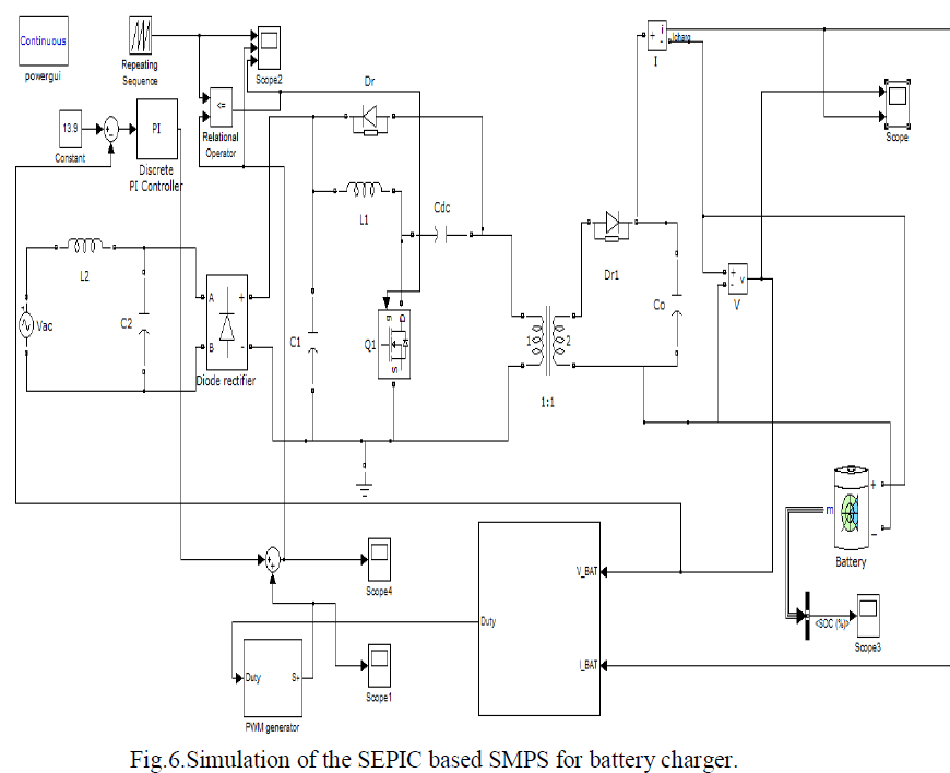
| The switched mode power supply based on SEPIC converter is simulated by using MATLAB software. It composed of SEPIC converter whose one of the inductor is made as a coupled inductor. The power factor corrected output is achieved by using PI and PID controller. By using these controllers the relation between the input and output voltage is controlled. The proportional integral controller checks the error between the actual and reference values of voltage and current based on the mode of operation. The error is compensated by using the integral controller and compared with the repeated sequence which is again compared with the PWM signal based on the duty ratio. By using the Boolean block the binary output is produced which can be used for logical operation. The generated pulses from the relational operator are given to the switching device. The simulation of the proposed system is depicted in the figure.6. |
 |
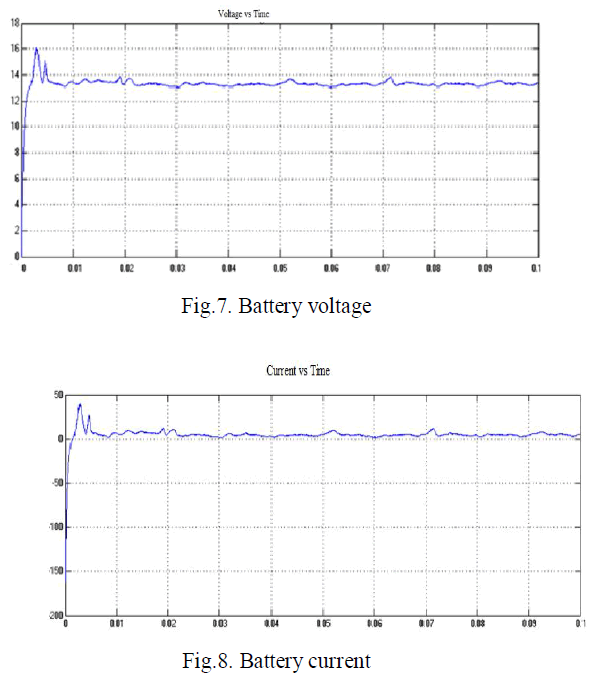 |
| Figure 7 and 8 represents the battery voltage and battery current. The battery voltage is maintained between 13.7V- 13.9V and battery current 2-3amps. Thus the desired output is achieved with the minimum losses and high efficiency. |
CONCLUSION |
| This paper proposes a battery charger based on the SEPIC PFC with the PI and PID controller. The efficiency of the proposed system is improved from 95% to 97% (6% improvement) which is higher than the conventional technique, in which the efficiency improvement is about 4.4%. This system introduces a new technique, which allows the dc link voltage to track the variation of the entire battery pack voltage (9V-38V). With this approach the losses and the cost of the entire system is reduced which in turn is very much suitable for charging applications. By eliminating the Fullbridge LLC converter the complexity of the circuit gets reduced. The proposed system is simulated by using the MATLAB tool and their performance is studied. |
References |
|