ISSN ONLINE(2278-8875) PRINT (2320-3765)
ISSN ONLINE(2278-8875) PRINT (2320-3765)
Geethu Biju Kumar1, Baby Sebastian2, Beena M Varghese3
|
| Related article at Pubmed, Scholar Google |
Visit for more related articles at International Journal of Advanced Research in Electrical, Electronics and Instrumentation Engineering
This paper describes the compensator design of Brushless DC motor based actuator in a position servo system. The work aims to develop the model of a BLDC motor presently used in launch vehicle application using the given specifications and design the suitable compensator in order to meet the requirements of launch vehicle. The servo analysis, compensator design and linear modelling of the electromechanical actuation based system are carried out. Compensation scheme is developed based on plant requirements and dynamics. Open loop plant and step response is observed. After compensation the system is found to meet all the requirements needed for launch vehicle applications. The simulation results are presented by using MATLAB/SIMULINK as the simulation tool.
Keywords |
| EMA, Compensator design, Servo design, Step Response. |
INTRODUCTION |
| Actuators are one of the key components contained in any industrial system. Electromechanical actuators are used in the industry for a variety of applications. In aerospace industry they are mainly used in flight control system of aircrafts, missiles and launch vehicles. Electro-mechanical Actuators are used in a variety of aerospace applications, from civilian airliners to robotic spacecraft [3]. |
| In this paper, an electromechanical actuator based position control system is presented. The electromechanical actuation system considered here is a BLDC motor based position servo system that consist of the main drive element BLDC torque motor and a high precision ball screw mechanism in closed loop position control to achieve best accuracy. The measurement system consists of an LVDT for position measurement. In overall the entire work involved in this project may be outlined into modelling of actuator, design of compensator, simulation analysis and performance Evaluation. |
SYSTEM DESCRIPTION |
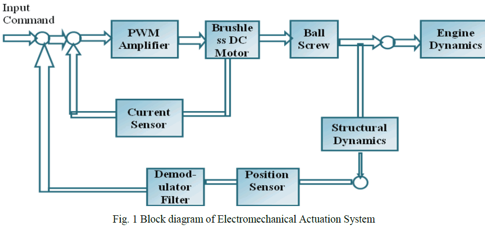
| The actuator under consideration is a linear electromechanical actuator based on a brush less DC torque motor. The block diagram of the linear actuation system driving the load is given in fig 1. It represents a closed loop position control of a BLDC torque motor powered from a DC source. Triple redundant LVDTs are used to sense the angular position of nozzle. The angular position is compared with a voltage equivalent to the desired displacement, command input. The resulting error voltage is amplified, compensated and fed to the BLDC torque motor, which produces the opposing moment torque about the nozzle pivot [point to nullify the error signal. The necessary power amplification of the control signal is given by PWM amplifier. A high gain current loop is provided to get a steady current corresponding to control voltage, which eliminates the nonlinearities in the PWM amplifier and rejects the power supply variations. The moment of inertia JM of the motor is .0055 kgm2 and the viscous damping coefficient of the motor BM is 0.002 Nm/rad/s. The current loop ensures the desired current through the motor armature coils as per the reference control signal at the input of the current loop. The demodulator will extract the only the original information from the position sensor output. |
 |
COMPENSATOR DESIGN |
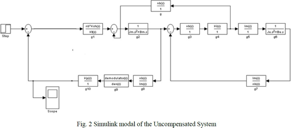 |
| Parameter values for the Uncompensated System are given by: |
 |
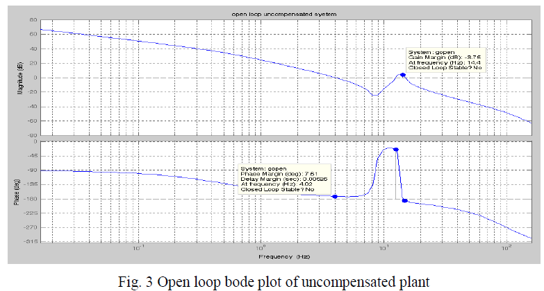
| Fig 2 shows the open loop bode plot of the plant. From figure the phase margin and gain margin of the system are: |
 |
| From the phase margin it is observed that even though it is positive, its value is very less so the system may not be completely closed loop stable. |
 |
A. Desired Frequency and Step Response Specifications |
| For launch vehicle applications the system need to meet certain closed loop frequency specifications and time specifications. They are: |
| Frequency response specification:- |
| -3dB Bandwidth= 4.5+/-0.5 Hz |
| -90 deg Bandwidth= 4.0+/-0.4 Hz |
| Maximum peak < 2dB |
| Step Response specification:- |
| Rise time= 70+/-20 msec |
| Overshoot < 25% |
| Settling Time < 500 msec |
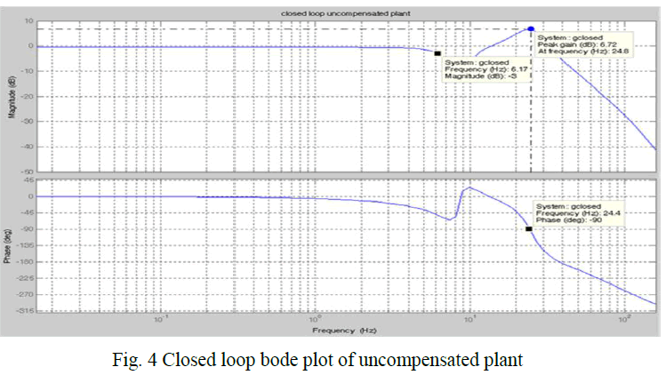
| The frequency response specification can be obtained by taking the closed loop response of the system. Fig.4 shows the closed loop response of the plant from which it is the following frequency response specifications are obtained: |
| Peak Gain= 6.72 dB |
| -3dB Bandwidth= 6.17 Hz |
| -90 deg Bandwidth= 24.4 Hz |
| These values shows that the given system specifications does not meet the desired requirements for the launch vehicle applications. |
 |
| Similarly the time specifications of the system are obtained by taking the step response of the system. Fig.5 shows the step response of the plant from which it is the following time specifications are obtained: |
| ïÃâ÷ Peak Amplitude= 6.1 dB |
| ïÃâ÷ Overshoot=inf |
| These values also shows that the given system specifications does not meet the desired requirements for the launch vehicle applications. And also from the step response it can be clearly observed that the system is having oscillations i.e. it is not closed loop stable. |
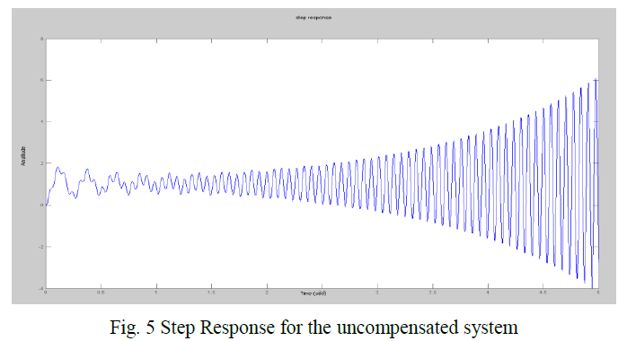 |
| From the frequency and step response for the uncompensated system it is obtained that the system does not meet the required specifications for the system to be stable. It is also found out that the uncompensated system is not completely stable. It has got large oscillations. Therefore in order to make the system closed loop stable and to meet all the specified requirements a suitable compensation scheme is provided. |
B. Compensation Scheme |
| The compensation scheme is designed as per the requirements and plant dynamics. As the phase margin of the system is less, in order to increase it a lead compensator can be introduced in the feed forward path. But while inserting a lead compensator it is seen that the phase margin of the system is increasing but also there is an unnecessary increase in the gain of the system at high frequency. Increasing the gain will decrease the stability margin. Thus system can be closed using a rate filter which have same function as a lead compensator without increasing the gain. |
| For the rate filter the rate is derived from the position sensor output. Increasing the coefficient of rate feedback will tend to make the overshoot lower but the system will be unacceptably sluggish. So there requires cascading a compensator in the forward path. As the specifications have not been fulfilled even by using rate feedback, a lag compensator is added in series in the forward path and along with the rate feedback. |
C. Lag Compensator |
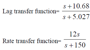
| Lag compensators are essentially low-pass filters. Therefore, lag compensation permits a high gain at low frequencies (which improves the steady-state performance) and reduces gain in the higher critical range of frequencies so as to improve the phase margin. It also reduces large steady state error in the system. |
| Thus the recommended compensation for a position servo loop is provided by lag compensator in the forward path which provides large steady state servo gain and rate filter in the feedback path which provides more relative stability to the rigid body servo mode. In Fig. 6 such a position controller is designed with lag and rate filter output. |
 |
D. Adding a notch Filter |
| A notch filter is also provided in the forward path of position loop to suppress the excitation of this mode. If there are disturbances in the system at a particular frequency, adding a Notch Filter can attenuate the gain of the system at that frequency. Consider the notch filter transfer function: |
 |
| The three adjustable parameters are ξ1, ξ2, and ωn. The ratio of ξ2/ξ1 sets the depth of the notch, and ωn is the natural frequency of the notch. |
| The notch filter is designed with -20dB attenuation at resonant (natural) frequency i.e. 13.6 Hz. The coefficient of numerator is selected as .05 and that of denominator is selected as 5. The notch filter expression is given by: |
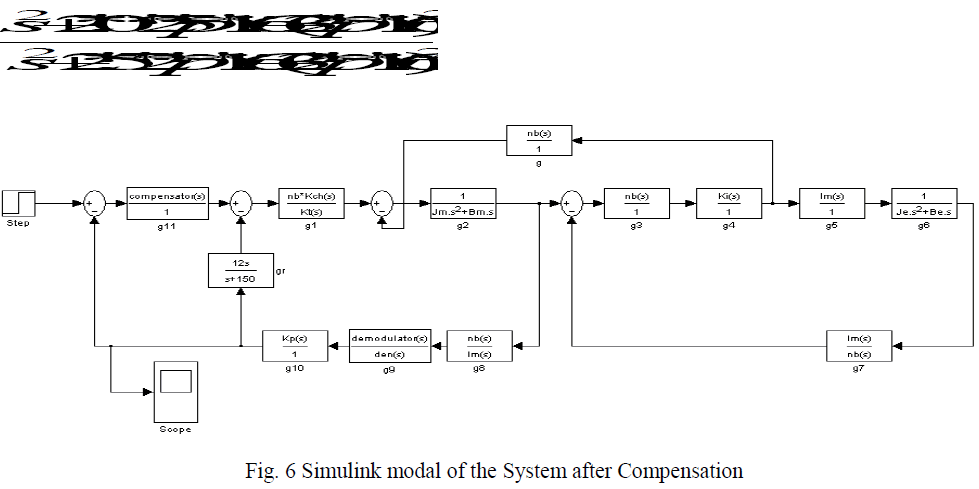 |
| Fig 6 shows the simulink modal of the system after compensation. In figure block „grâÃâ¬ÃŸ shows the rate filter inserted in feedback path and block g11 shows the position loop compensator which includes both lag compensator and notch filter. After applying compensation the open loop bode of the system is obtained as: |
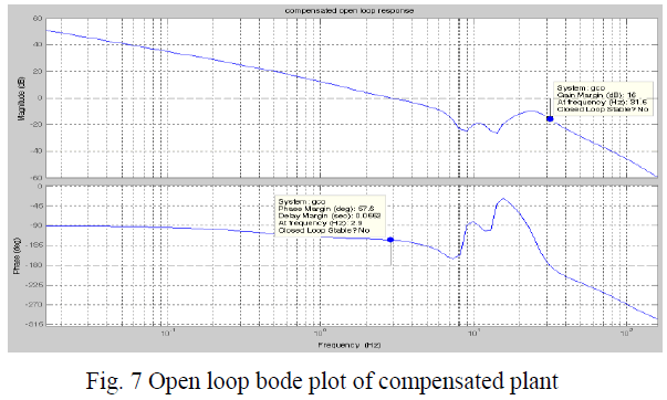 |
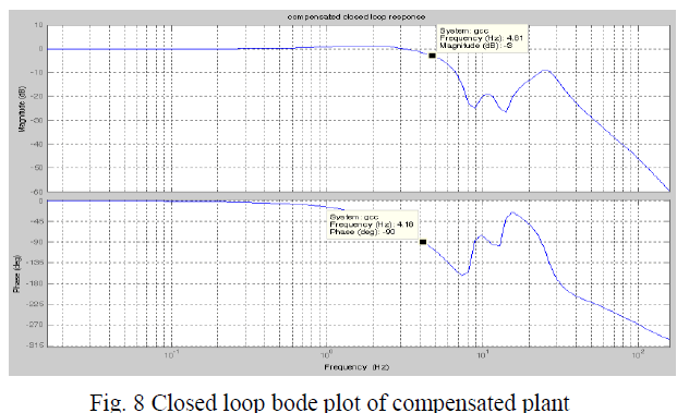
| It is seen that now the phase margin of the system has improved to a desirable value without much increase in gain of the system. From the closed loop response of the compensated system the frequency response specification of the system are noted they are within the required specifications. |
| The frequency response specifications of the compensated system areas obtained by the closed loop response are: |
| -3dB Bandwidth= 4.81 Hz |
| -90 deg Bandwidth= 4.18 Hz |
| Maximum peak = 1.2dB |
 |
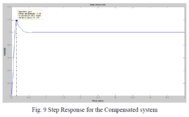
| Similarly, from the step response of the compensated system the time specifications of the system are noted and it is seen that they are also within the required specifications. |
| From the Step Response for the Compensated system the time response specifications of the compensated system are: |
| 1) Rise time= 76 msec |
| 2) Overshoot = 20% |
 |
CONCLUSION |
| Electromechanical actuation system using a BLDC motor is considered. The servo analysis, compensator design and linear modeling of the electromechanical actuation based system are carried out. Compensation scheme is developed based on plant requirements and dynamics. The preliminary analysis shows that the plant has the capability to meet the specification and it is possible to stabilize the system. Open loop plant and step response is obtained. The system is found to meet all the requirements needed for launch vehicle applications. The simulation results are presented by using MATLAB/SIMULINK as the simulation tool. |
References |
|