Research & Reviews: Journal of Engineering and Technology
ISSN: 2319-9873
ISSN: 2319-9873
Department of Electronics Engineering, Mount Zion College of Engineering, Kadammanitta, Pathanamthitta, India
Received date: 20/12/2016; Accepted date: 13/02/2017; Published date: 19/02/2017
Visit for more related articles at Research & Reviews: Journal of Engineering and Technology
The launch vehicle is steered in pitch, yaw and roll directions by means of thrust vector control of servo actuators of Engine Gimbal Control (EGC) System that provides precise steering for the missile platform. The EGC actuation system is widely used for the thrust vectoring of liquid propellant engines of launch vehicle, that carry a payload from earth’s surface to outer space. This paper deals with the compensator design methodology suitable for the EMA based position servo system, so as to meet the desired frequency and time domain requirements of the EGC system. It involves servo analysis, linear modeling and compensator design of the electromechanical actuation system. Linear model of a servo actuation system is has been developed and design of compensator is carried out so as to meet, the requirements of launch vehicle EGC system. The simulation results are presented using MATLAB/SIMULINK as the simulation tool.
EMA, EGC system, Thrust vector, Compensator design
Be: Viscous damping coefficient of engine gimbal
Bm : Viscous damping of torque motor
Je: Engine Moment of inertia (MI)
Jme : Reflected MI from rotor to engine side Jme
Jm: MI of torque motor Rotating Assembly
Kb : Torque motor back emf constant
Kcf : Current loop feedback gain
Kl: Actuator mounting structure stiffness
Kp: Position sensor (LVDT) scalar factor
KT: Torque sensitivity of motor
Lm: Actuator lever arm length
nb: Ball screw gear ratio
Nch: Number of operating channels of torque motor
Rm: Torque motor winding resistance
Vs: Torque motor supply voltage
ωd: Demodulator frequency
ξd: Demodulator damping factor
In launch vehicles, a small rotation of the thrust vector angle about the gimbal (typically between ±8° and ±5° in pitch and in yaw) is sufficient to generate a significant amount of normal or lateral force at the gimbal, that can be used to stabilize and steer the vehicle to overcome the wind-gust disturbances and balances the aerodynamic moments. A linear actuation system plays critical role in thrust vector control of space transportation systems. Linear actuators could either be fluid power actuators like pneumatic or hydraulic actuators or could be motor powered like electromechanical actuators. The electro-mechanical actuators [1] are being scrutinized for the design of servo actuation system in an effort to provide lighter, cleaner and more reliable control actuators.
During the flight, the flight control system and the actuators are commanded by the autopilot (DAP) to either extend or retract the actuator shaft, via electro mechanical actuation to achieve the desired pitch and yaw changes in engine rotation and hence achieve the required nozzle deflection. The stage-2 EGC servo-actuator system provides two orthogonal.
Electromechanical actuators (Figure 1) that controls the deflection of the engine. One of the actuators is in the pitch direction whereas the other in the yaw direction. The vehicle is attached to one end of the actuator and other end is attached to the nozzle. The roll movement is achieved with the help of separate roll control system [2].

Figure 1: Engine gimbal control (egc) actuation system.
The paper is organized as follows. In Section 2, the functional model of EGC system is presented. The Linear model of stage -2 EGC system is included in section 3. In the section 4 compensator design methodology is detailed. The Simulation [3] results are also presented in section 4.The concluding remarks are given in Section 5.
The actuators are commanded by the autopilot, for the movement of engine dynamics [4] based on the error commands generated by the navigation and guidance system.
The electro-mechanical servo control systems [5] consist of a torque motor that generates sufficient torque to drive the nozzle about the gimbal point. Block diagram of typical electro mechanical actuator based EGC system is shown in Figure 2. By means of ball screw mechanism, the rotary torque is converted into linear force, which in turn drives the engine nozzle. The deflection of the nozzle is measured by the position sensor (LVDT) and the output of the LVDT is processed and compared with a voltage equivalent command from DAP, for the desired displacement. The resulting error voltage is amplified, compensated and fed to the BLDC torque motor, which produces required torque moment about nozzle pivot point to gimbal the engine. The current loop ensures the desired current through the motor armature coils as per the reference control signal at the input of the current loop.

Figure 2: Functional model of EMA based engine gimbal control system [6].
The EGC system has been modeled as a system comprising of four independent actuators, two in the yaw axis and two in the pitch axis. The servo development and analysis of each of the actuators are done independently. The electromechanical actuator (EMA) for stage-2 EGC system is mathematically modeled, and it is approximated as a second order linear system expressed as follows:
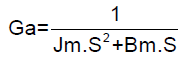 (1)
(1)
The load dynamics of stage-2 EGC actuator is inertia dominated system and the transfer function of load/nozzle dynamics is given by equation (2).
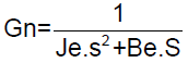 (2)
(2)
The mechanical resonance between the equivalent moment of inertia and stiffness can be derived to given the following resonance frequency (fr) and the dip frequency (fdip).
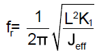 (3)
(3)
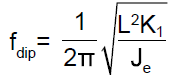 (4)
(4)
Jeff is the equivalent moment of inertia derived from engine moment of inertia and motor rotating moment of inertia.
The equivalent moment of inertia (Jeff) is expressed in Eq (5):
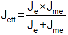 (5)
(5)
Where Kl is the equivalent mounting bracket stiffness, L is lever arm length, Jm is the engine moment of inertia and Jme is the reflected moment of inertia of rotor to engine side (Figure 3).

Figure 3: Linear model of stage-2 EMA based EGC system.
The compensation scheme of stage-2 EGC system has been developed based on the requirements and plant dynamics, available during the design phase. The stability requirements are stated in the form of gain margin (GM > 6dB) and Phase margin (PM >40°). The individual Frequency response of Electro Mechanical Actuator (Figure 4) and Nozzle dynamics (Figure 5) is analyzed via bode plot analysis [7,8].

Figure 4: Frequency response of EM actuator.

Figure 5: Frequency response of nozzle dynamics.
From the frequency response analysis of open loop system (Figure 6) it is found that even though the system is stable, the system specifications are not met. The compensator methodology is employed so as to meet the closed loop specifications.

Figure 6: Frequency response of open loop uncompensated system.
Compensation Scheme
The compensation scheme comprised of a pseudo rate loop and a position loop, as shown in the Figure 7. The position loop compensator consists of a notch filter, lag filter and an appropriate gain.

Figure 7: Compensation scheme for EGC system.
From the Figure 6, it is clear that the phase margin of the system is less compared to the required system specification. A lead compensator can be introduced in the feed forward path so as to improve the phase margin. But the Lead filter in the feed forward path differentiates the incoming signal and the noise signal may also get amplified, if present; introduces negative impact on the dynamic performance of the system. So that a Rate filter in the feedback path is the better choice for the same.
Ratefeedback Compensation
Plant parameter uncertainty and the sensor noise tend to increase at high frequencies. To avoid unwanted control action at these frequencies, the rate feedback compensator should be designed that shapes the loop response above crossover frequency. In the actuator-nozzle system, velocity is not directly available as a signal to be fed back. Hence a pseudo rate loop is employed in which the rate signal is derived from position sensor (LVDT) output. The rate filter transfer function is expressed as follows:
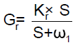
The numerator of the rate loop compensator is kept Kr ×S and denominator is selected in such a way to obtain rate loop bandwidth about four to five times that of the position loop. Increasing the coefficient of rate feedback will tend to make the overshoot lower but the system will be unacceptably sluggish. So that a lag compensator is cascaded in series with this in the forward path, in order to meet the system specifications.
The Figure 6 shows the open loop frequency response of the plant with the resonant peak at 17.3Hz (theoretically obtained by the Equations 3 and 4). The resonance mode is actively stabilized using a pseudo rate loop in which rate input is derived from the position sensor output (Figure 8). The pseudo rate loop also provides more relative stability to the rigid body servo mode.

Figure 8: Frequency response of open loop and rate closed system.
Lag Filter
The position loop also consists of a lag filter to ensure good steady state response. The general transfer function of the lag filter is:

Where,  The Lag compensator is essentially a passive low pass filters (LPF) which ensures high gain at low
frequencies (that improves the steady-state performance) and reduces the gain in the higher critical range of frequencies so as
to improve the phase margin.
The Lag compensator is essentially a passive low pass filters (LPF) which ensures high gain at low
frequencies (that improves the steady-state performance) and reduces the gain in the higher critical range of frequencies so as
to improve the phase margin.
Notch Filter
A Notch filter is also introduced in the forward path of the position loop; suppress the high frequency vibration mode associated with the mechanical systems. So the notch filter centered at resonant frequency (17.3 Hz) attenuate control structure interaction. A wide notch filter is preferred so as to avoid resonant frequency variation under aero dynamic loading. Consider the notch filter transfer function as follows.
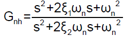
Here the three adjustable parameters are ξ1, ξ2 and ωn. The ratio of ξ2/ξ1 sets the depth of the notch, and ωn is the natural frequency in radians.
The Figure 9 shows the response of notch filter designed centered at the resonant (natural) frequency i.e., 17.3 Hz and the coefficient ξ1 is selected as 0.05 (Table 1) and that of denominator ξ2 is selected as 0.5 (Figures 10-12).

Figure 9: Frequency response of notch filter.

Figure 10: Frequency response of rate closed and closed loop system with and without notch filter.

Figure 11: Frequency response of compensated closed loop system.

Figure 12: Step response of compensated closed loop system.
| Specification | Requirement | Measured value |
|---|---|---|
| -3 dB bandwidth | 4.5 ± 0.5 Hz | 4.2 Hz |
| Rise Time | 70 ± 20 ms | 81.2 msec |
| Peak Time | <180 | 170 msec |
| Settling Time | <600 msec | 111 msec |
| Overshoot | <25% | 21% |
| M-Peak | <2 dB | 1.6 dB |
| Steady state error | <2% | 0 |
Table 1: Performance evaluation of the compensated actuation system.
The paper deals with the compensator design methodology suitable for the linear model of launch vehicles EGC system, for the thrust vector control applications. Compensation scheme is developed based on plant requirements and dynamics that satisfy all the frequency and time domain requirements of the system. The simulation results are presented using MATLAB/SIMULINK as the simulation tool. The control system compensation, improves the dynamic performance of the system in order to mitigate some of the undesirable features of the control elements present in the EGC actuation system.