ISSN ONLINE(2278-8875) PRINT (2320-3765)
ISSN ONLINE(2278-8875) PRINT (2320-3765)
| P.A. Ambresh1, P. M. Hadalgi2 Microwave Research Laboratory, Department of Applied Electronics, Gulbarga University, Gulbarga-585106, India |
| Related article at Pubmed, Scholar Google |
Visit for more related articles at International Journal of Advanced Research in Electrical, Electronics and Instrumentation Engineering
A new design of microstrip antenna with short stubs placed along the radiating edges of patch have been studied and results are presented. By inserting stubs of proper dimensions on the patch surface, a bandwidth of 200 MHz (6.67 %) with a gain of 5.00 dB is achieved. Results also indicate that, at resonated frequency, the proposed design has good omni-directional radiation characteristics by the use of coax feed technique with physical size reduction of about 16 %.
Keywords |
| Resonance, short stub, antenna, radiating edges, impedance bandwidth. |
INTRODUCTION |
| microstrip or patch antenna is a low profile antenna and have become very significant in modern wireless communication applications. Microstrip antennas, such as microstrip patch, stub loaded patch antennas and slot antennas are found attractive for use in many applications because they are lightweight, conformable and easy to integrate with monolithic microwave integrated circuits (MMICs). Various techniques have been studied, which provide a better bandwidth in case of microstrip patch antennas and also have been developed [1-3]. Along with the above mentioned advantages, the reduction in physical structure i.e., compactness [4-9] of microstrip patch antenna (MPA) is also an essential requirement in many practical applications. |
| Compact multimode patch antennas for application in medium size MIMO terminals combining spatial and radiation pattern diversity is designed by Eva Rajo-Iglesias et al [10] and the design achieved 2.5 % bandwidth. A shorted square-ring slot antenna with a branched slot for the 1575 MHz and 2.4 GHz is developed and achieved a bandwidth of 4.5 % [11]. A planar triple-frequency antenna developed to quad-frequency shorted MPA at frequencies 0.9, 1.8, 2.4, and 5.4 GHz has been studied [12] and this design has achieved a bandwidth of 12 MHz. This paper presents the use of stubs on the patch surface which provided improved bandwidth characteristics of 200 MHz with a moderate gain suitable for S-band applications. The details of the antenna structure and results are also provided. |
SINGLE ELEMENT ANTENNA STRUCTURE AND EXPERIMENTAL RESULTS |
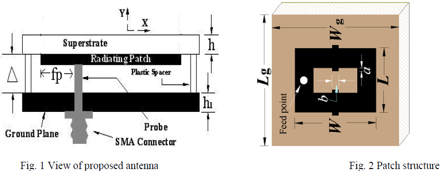
| The structure of the proposed antenna supported on a copper ground plane by the use of silicon spacers is shown in Fig. 1. The rectangular patch is fabricated on FR4 dielectric material having thickness h = 0.16 cm and has dimensions in length L = ïÃÂìo/4.39 and width W = 0.299ïÃÂìo. where λ0 is the operating wavelength. Patch also consists of the short stubs with dimensions a = 1 mm and b = 2 mm are placed along the radiating edges of the patch as shown in Figure 2. The use of stubs is to achieve the improved bandwidth, gain and compactness (physical size reduction). The ground plane used in this design is a copper plate with thickness h1 = 1.6 mm having dimensions Lg = Wg = 35 mm and is placed at a distance Δ = 8.5 mm below the superstarte as shown in Fig. 1. |
| For better impedance matching, coax feed technique is used. The characteristics of the antenna are also sensitive to the antenna design parameters such as length, width and air gap. In this case, the proposed antenna leads to impedance matching in a wide-frequency band with moderate gain characteristics. As the patch is excited through coax feed technique, the feed point is placed along the centre line of Y-axis at a distance fp = 4.2 mm. All the fabricated patch antenna and slot dimensions are functions of λ0, where λ0 is the operating wavelength. |
 |
| The return loss (RL), impedance plot and VSWR characteristics of the proposed antenna are measured on Vector Network Analyzer (Rohde and Schwarz, Germany make ZVK model 1127.8651) and the far-field pattern is measured using STIC turn table. A FR- 4 dielectric material, which is available at a much lower price, is used instead of expensive substrate material. |
 |
 |
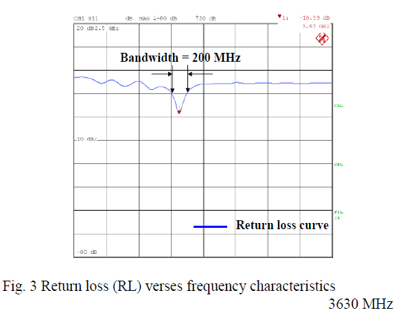
| Although the use of a high relative permittivity substrate usually restricts the bandwidth, the experimental bandwidth (with 3630 MHz center frequency) is approximately 200 MHz (6.67 %, RL= -18.59 dB) covering frequency range 3500 – 3700 MHz for return loss (RL) less than -10 dB with single resonance characteristics. The return loss versus frequency diagram is as shown in Figure 3. The patch antenna incorporated with the short stub introduces a capacitance that suppresses some of the inductance introduced by the feed due to the thick substrate, and a single resonance of stub is obtained. Hence, the design parameters of the antenna lead to good impedance matching in an S-band frequency. |
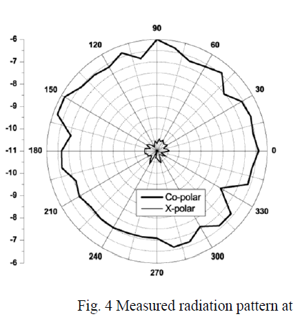
| After completing the calibration by using a horn antenna, the far-field radiation pattern is measured. Figure 4 presents the radiation pattern measured at center frequency 3630 MHz for the proposed antenna. It is found that throughout the band, the pattern is omni-directional in nature. The cross-polarization level is less than -10 dB in the same frequency. |
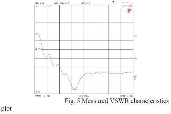
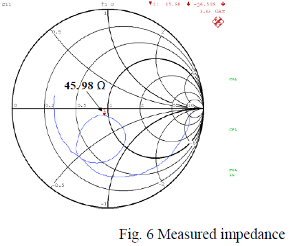
| The measured gain for the proposed antenna is 5.00 dB over the entire band with compactness of 16 % compared to simple microstrip patch antenna. Figure 5 shows the VSWR characteristics and it is found to be 1.426 which is less than 1.5 at resonant frequency 3630 MHz signifying less reflected power over the entire band. Figure 6 shows the impedance plot measured at 3630 MHz showing an impedance of 45.98 Ω + (-j6.549) between the input and load with a single loop characterizing single resonance. |
 |
 |
CONCLUSION |
| By using the design parameters given above, the patch antenna with wideband characteristics has been studied. The antenna exhibited wideband along with moderate gain characteristics. The measured bandwidth is 200 MHz (for return loss less than -10 dB) with 13 % compactness. However, the proposed antenna obtained not only wide bandwidth, but also has gain of 2.00 dB with omni-directional radiation characteristics. As this antenna is wide band, low profile and light weight, it finds applications in WiMax, maritime mobile services and wideband communication systems in S-band frequency. |
ACKNOWLEDGMENT |
| Authors gratefully thank the Department of Science and Technology (DST), Government of India, New Delhi, for sanctioning Vector Network Analyzer to this Department under FIST Project and also providing financial assistance under Rajiv Gandhi National - Junior Research fellowship (RGN-JRF) [No.F.14-2(SC)/2009(SA-III) dated 18 November 2010] scheme by University Grants Commission, New Delhi, India. |
References |
|