International Journal of Advanced Research in Electrical, Electronics and Instrumentation Engineering
ISSN ONLINE(2278-8875) PRINT (2320-3765)
ISSN ONLINE(2278-8875) PRINT (2320-3765)
G.Pradeep Sagar1, K.Roopa2, M.Rajasheker Reddy3
|
| Related article at Pubmed, Scholar Google |
Visit for more related articles at International Journal of Advanced Research in Electrical, Electronics and Instrumentation Engineering
Now a days the use of multi level inverters are increasing day to day life and they playing a vital role in case of medium and high power applications due to having less harmonic content compared with classical inverters. In this paper a comparison study is made between symmetrical and asymmetrical cascaded H-bridge multi level direct torque (DTC) induction motor drive. In this case, symmetrical and asymmetrical arrangements of seven and nine-level H-bridge inverters are compared in order to find an optimum arrangement with lower switching losses and optimized output voltage quality. The simulation results shows that an asymmetrical configuration provides more voltage levels with very low distortion, using less switching devices. Moreover, torque ripples are greatly reduced.
Keywords |
| Direct torque control (DTC), induction motor, multilevel inverters |
INTRODUCTION |
| Multi level voltage source inverters are applicable for high voltage and medium power standard drive applications. Multi level inverters are available for medium voltage industrial applications. In order to limit the motor winding insulation stresses and to reduce the harmonics the inverter output has more number of levels. So in order to increase the inverter output levels there is a increase in switching devices causes the reduction in efficiency and power converter overall reliability. On the other hand if the numbers of inverter output levels are low then it causes the use of a large expansive LC output filter to reduce the stresses on motor winding. |
| The multi level inverters are classified in to three types those are Cascaded H-Bridge and diode clamped and final one is flying capacitor type. In diode clamped multi level inverters except in 3-level circuit, they do not share capacitor voltages automatically. So it needs some form of extra balancing circuit. In addition to this as the number of levels increases, some diodes have to block large voltages. This makes this type of multi level inverters unattractive for more than 5-levels. |
| In flying capacitor multi level inverters, the flying capacitors need to be pre-charged to half of d.c supply voltage. The switching strategy must be used to maintain flying capacitors at the correct voltage. This must be done with some form of feedback mechanism. As the number of levels increases in the flying capacitor circuit arrangement the number of capacitors required also increases rapidly. This circuit also difficult to built. |
| Cascaded H-Bridge multi level inverter is considered because the device voltage sharing is automatic because of the independent pattern. So it is clear that is cascaded H-Bridge inverter is used. And the asymmetric configuration is easily possible to implement in cascaded H-Bridge inverter. |
| symmetrical multi level inverter all H-Bridge cells are supplied by equal voltages, then all the arm cells produces similar output voltage levels. However if all the cells are not supplied by equal voltages, then the inverter becomes asymmetrical one. In this case the arm cells have different effect on the output voltage. |
| In the linear range of modulation, the maximum value of obtainable voltage is 90.7% of the six step value. This voltage can be further increased by properly utilizing the D.C link capacity by using space vector pulse width modulation. |
 |
| In order to control the induction motor there are several methods among them the most effective one is direct torque control (DTC), now a day’s which is recognized as a high performance control strategy for A.C drives. Here in this paper a theoretical approach is used to design a strategy compatible with hybrid Cascaded H-bridge multilevel inverter, symmetrical and asymmetrical configurations are implemented and compared. A simulation result shows that asymmetrical inverter fed induction motor has good performance and very low torque ripples. |
II.CASCADED H-BRIDGES STRUCTURE AND OPERATION |
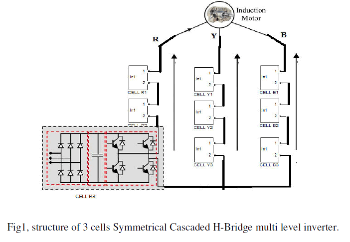
| The cascaded H-bridge inverter consists of power conversion cells, each cell is supplied by an isolated dc source on the dc side, here the dc source is obtained from batteries, fuel cells, or ultra-capacitors, and it is connected in series on the ac side. The advantage of this topology is that the modulation, control, and protection requirements of each bridge are modular. Fig. 1 shows a 3-phase topology of a cascade H-Bridge multi level inverter with isolated dc-voltage sources. An output phasevoltage waveform is obtained by adding the bridges output voltages and the equation for it is shown in below. |
| Vo(t)=vo,1(t)+vo,2(t)+·· ·+vo,N(t)…….. (1) |
| Here N is the number of cascaded bridges. The inverter output voltage vo (t) may be determined from the individual cells switching states and the equation for it is shown in below. |
 |
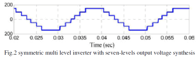
| In Fig. 1 if all dc-voltage sources are equal to Vdc, then the inverter is known as a symmetric multilevel one. The effective number of output voltage levels in m symmetric multilevel inverter is related to the cells number by |
| m = 1+2 N................................................ (3) |
| The maximum output voltage Vo, Max is then |
| Vo,MAX = NVdc................................... (4) |
| From the equation three it is clear that is the symmetrical configuration produces seven levels in the output phase voltage wave form and is shown in fig.2. Here in this configuration, it needs 3-cells in each phase. |
 |
| To increse number of output voltage levels, without increasing in number of cells asymmetric multi level inverter is used. For asymmetric case , it has been proposed that to choose the dc voltage sources according to geometric progression with a factor of 2 or 3. So for an N cascaded cells can achive the fallowing distinct voltage levels |
 |
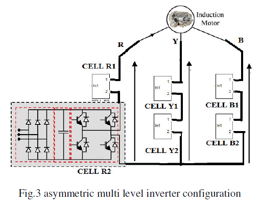
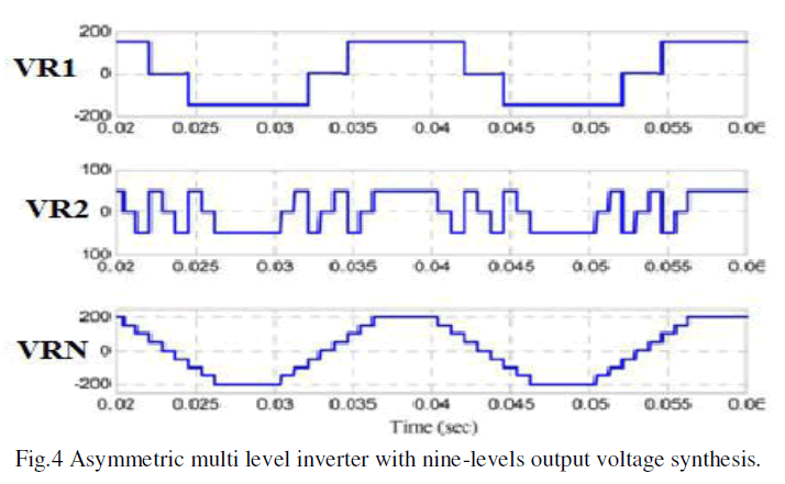
| Fig.3 shows the asymmetric multilevel inverter configuration and Fig.4 shows typical waveforms of fig.3 multi level inverter with, respectively, two dc sources (vdc and 3vdc). |
 |
| From the above figure it is clear that the switching devices are reduced and it is capable of producing nine-levels in the output phase voltage waveform. The maximum output voltage Vo, Max is then |
 |
 |
| From fig.1 and fig.3 it is clear that is asymmetric configuration provides more number of levels than symmetrical one with less number of switching devices and from equation 4 and equation 7 the asymmetric configuration provides maximum output voltage. |
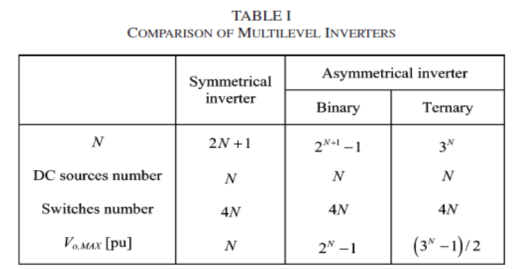
| Table .1 summerizes the number of levels, dc sources and switches and maximum available output voltages for Cascaded multi level inverter. |
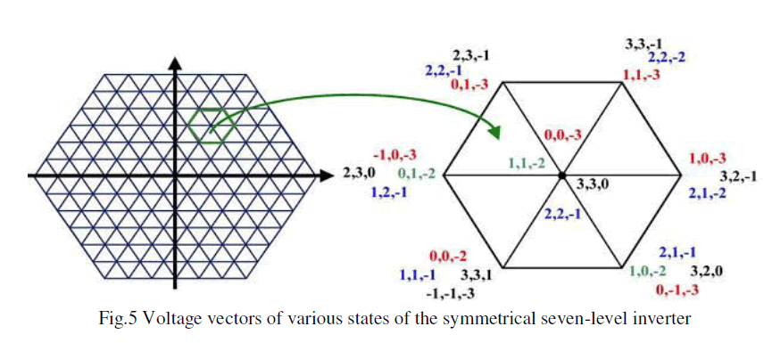
| Increasing in the number of levels produces more steps in the output voltage will be of higher resolution and hence the reference sinusoidal output voltage can be better achived. For an m-level inveter has m3 switching states and m-zero states, here zero output voltages are produced.So there are (m3-m) are non zero states, which are unique states and mutual states. The unique state produces voltage vectors that can not be produced any other states. On the other hand, the mutual state produces a set of output voltages that can be produced by some other mutual states or state. The eqivalent mutual states share the same voltage vectors. The m-level invereter has [(m-1)3-(m-1)] non zero mutual states.The voltage vectors of the seven-level inverter are shon in fig.5. The number of distinct voltage vectors obtained from m-level inverter is [m3-(m-1)3]. The presence of equivalent mutual states has usually been used to reduce the switching losses. So the equivalent mutual states can be replaced by any one of these states and the other states can be assumed as redundant. So for an m-level symmetrical H-Bridge multi level inverter has (m-1)3 redundent states. |
 |
 |
III.INDUCTION MOTOR DIRECT TORQUE CONTROL |
| Direct torque control technique is alternative method to flux oriented control. In standered version drives even at high samping frequncies important torque ripples are produced and inverter swithing frequency is variable and very dependent on the motor shaft speed and torque. Hence it causes production in torque harmonics with variable frequency and acoustic noise. The control strategy which is employed for the multi level inverter should reduce these drawbacks. |
1.NOMENCLATURE |
 |
| p =Pole pair number. |
2. TORQUE AND FLUX ESTIMATIONS |
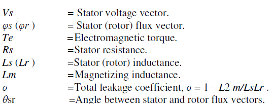
| In an induction motor the stator flux vector is related to stator voltage and stator current vectors given by |
| d φs/dt = vs(t)−Rsis(t)…………..(8) |
| In the above equation vs is constant over a sample time interval and neglecting the stator resistance then the stator flux is directly proportional to the stator voltage vector. So as the rotor flux rotates slowly, then stator flux can be changed quickly and the angle between both the vectors can be controlled directly by vs. The dynamic behavior and graphical representation is shown in fig.6 |
 |
| The relationship between stator and rotor flux shows that by keeping the amplitude of stator flux vector constant will produce a constant rotor flux vector. |
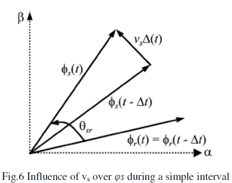
| The electromagnetic torque developed by induction motor is given by |
| Te =(3/2)P(Lm/ σLsLr) φsφrsinθsr……………(9) |
| From the above equation it is clear that is the changes in θsr is due to the effect of vs so there is a fast and direct changes in developed torque. So it is clear that is DTC technique uses this principles to achive the desired torque response for induction motor by applying appropriate stator voltage vector to correct the flux trajectory. |
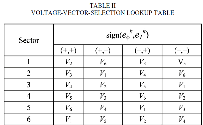
3. VOLTAGE VECTOR SELECTION |
| Fig.7 shows the one of the 217 voltage vectors generated by the inverter at instant t=k, denoted by vs k (central dot). The next voltage vector, to be applied to the load will be v s k+1 , is given by |
| Where Δ vs k = {vi |i = 1, . . . , 6}. Each voltage vector vi corresponds to one corner of the elemental hexagon shown in gray and by the dashed line in Fig. 7. |
 |
| The next task is to determine which v s k+1 will correct the torque and flux responses, knowing the actual voltage vector vs k , then the torque and the stator flux vector position (sector determined by angle θs ) and flux errors ek φ and ek T. Here it is important that the next voltage vector v s k+1 applied to the load will always be one of the six closest vectors to the previous vs k, this will soften the actuation effort and reduce high dynamics in torque response due to possible large changes in the reference. Table II shows the vector selections for the different sectors and comparators output (desired φs and Te corrections). |
| In order to implement the DTC of an induction motor fed cascaded H-bridge multi level inverter, one should determine the one should determine at each sampling period, the inverter switch logic states as a function of the torque and flux instantaneous values for the selection of the space vector in the α–β frame. Here the control algorithm was divided into two major parts which are executed independently in cascaded inverter. |
A) FIRST PART |
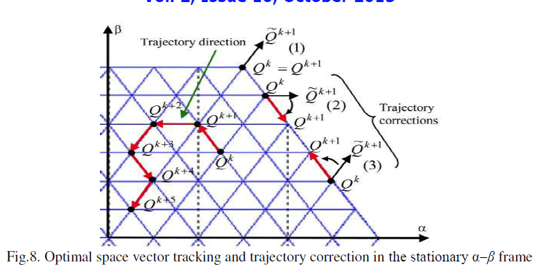
| The main intension of this part is to control the electromagnetic state of the induction motor. The torque and flux are always instantaneous values and their changes will be taken into consideration for the selection of space vector in the α–β frame. Once the space is chosen, the phase levels sequence can be selected. To implement this part, one should detect the position of the space vector in the α–β frame (Qk at sampling time k). In order to reduce voltage steps magnitude the next position Qk+1 to be achieved before next sampling instant k + 1 (see Fig. 8). Here per sampling period Ts only one step displacement in the α–β frame is authorized. Hence, the Qk+1 must coincide with one of the six corners of the elementary hexagon centered at Qk , in order to avoid the inverter saturation. The same procedure will be adopted for the next sampling period in order to determine the next trajectory direction, yielding Qk+2, which in turn will coincide with one of the six corners of the new elementary hexagon centered at Qk+1. In the presence of inverter saturation (if Qk gives an not reachable point for Qk+1), a trajectory correction is necessary (see Fig. 8). In cases (2) and (3), the closest displacement direction is selected. Case (1) illustrates a particular situation in which no switching should be performed, since the nearest reachable trajectory goes roughly toward the opposite sense of the favored one given by the lookup table (see Table II). |
 |
B) SECOND PART |
| It makes the full use of the multilevel topology to choose the phase levels sequence that synthesizes the voltage vector selected previously. There are several phase levels sequences that are able to generate the same vector this degree of freedom can, therefore, be used to reduce voltage steps magnitude according to one of the following criteria: i) minimize the commutation number per period; ii) distribute commutations for the three-phases per period; or iii) choose a vector which minimizes the homopolar voltage. This part allows losses and torque ripple minimization. Finally, the configuration of each phase will be selected and must be able to generate the phase levels. |
 |
IV. SIMULATION R4ESULTS |
 |
 |
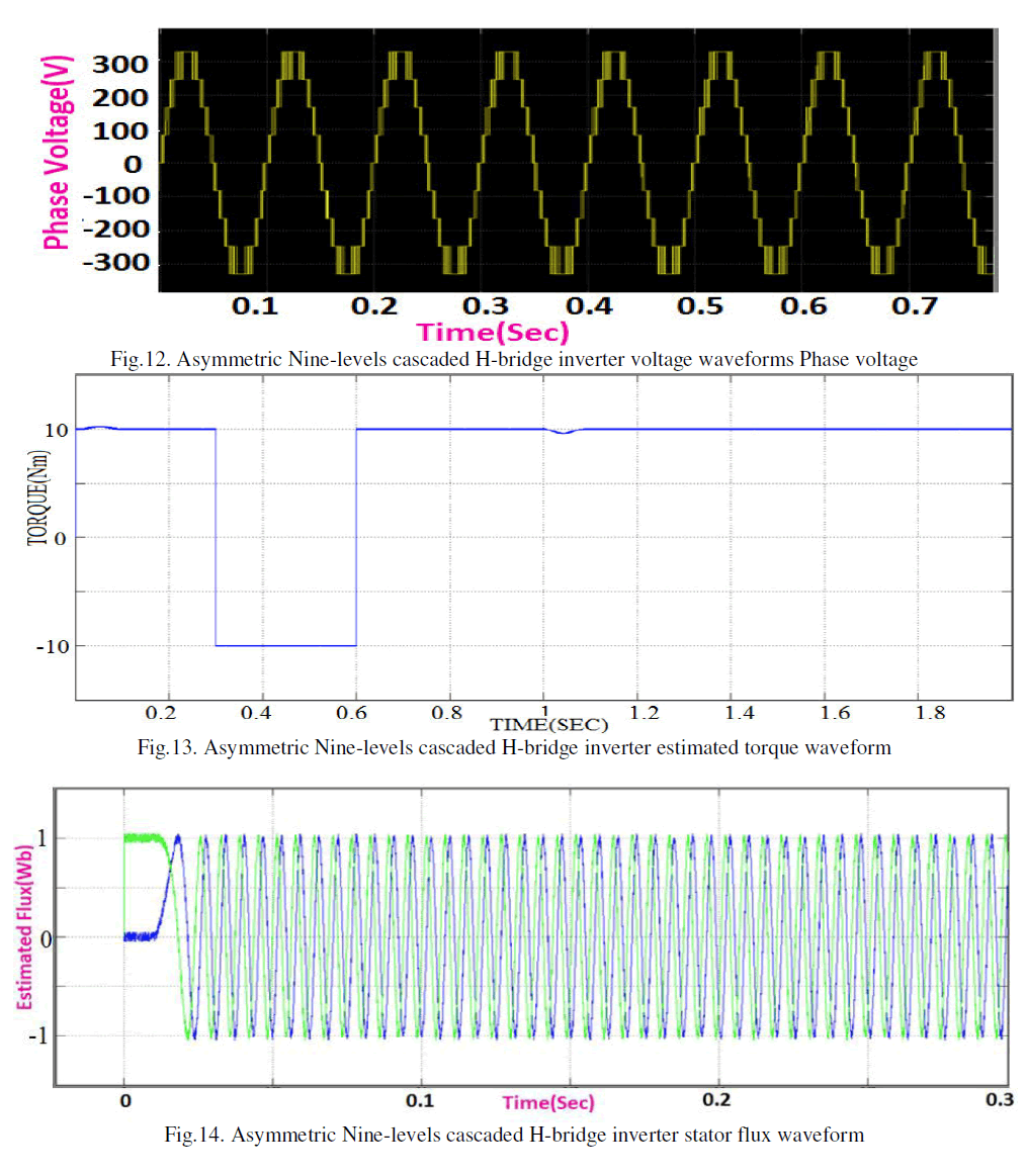 |
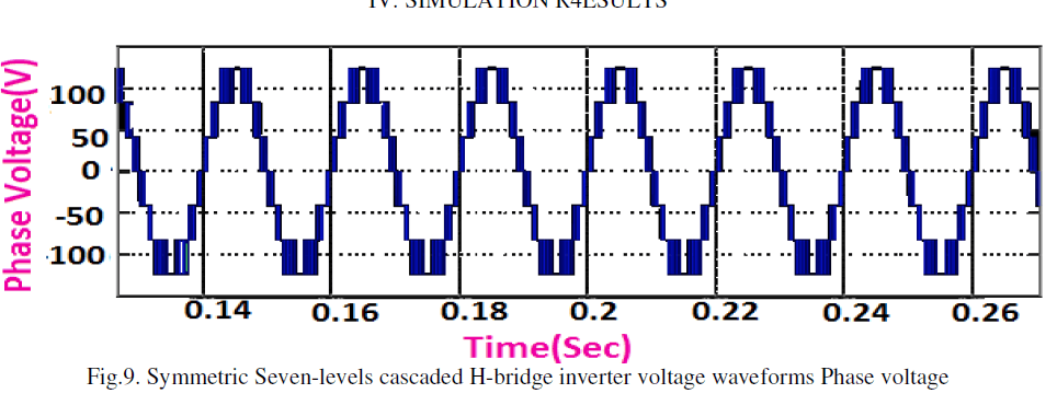
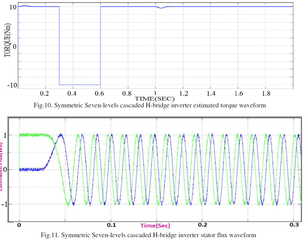
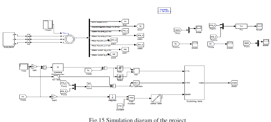
| Fig.9-11 are the simulation results of Seven- level symmetrical inverter wavefoms and Fig.12-14 are the simulation results of Nine- level asymmetrical inverter waveforms.By comparing fig.9 & fig.12 it is clear that the number of levels are increased and maximum output phase voltage is attained by Asymmetric configuration only. The main objective of the paper is reducing the harmonics by using less switching Devices and by increasing number of levels. From the waveforms it is clear that is asymmetric inverter produces nearly sinusoidal waveforms. The Simulation diagram of this paper is illustrated in fig.15. |
V.CONCLUSION |
| This paper dealt with a simulation and comparision of cascaded H-bridge multilevel DTC induction motor drive. Here in this paper symmetrical and asymmetrical arrengements of seven and nine-levels H-bridge inverters have been compared in oreder to find optimum arrengement with lower switching losses and optimized output voltage quality. |
| The simulation results shows that an asymmetrical configuration provides nearly sinusoidal voltages with low harmonics and distortion, using less switching devices. Here by using asymmetric configuration torque ripples are greatly reduced and it enables a DTC solution for high power induction motor drives. |
 |
References |
|