ISSN ONLINE(2320-9801) PRINT (2320-9798)
ISSN ONLINE(2320-9801) PRINT (2320-9798)
Dr.R.Seyezhai1, R.Anitha2, S.Mahalakshmi3, M..Bhavani4
|
| Related article at Pubmed, Scholar Google |
Visit for more related articles at International Journal of Innovative Research in Computer and Communication Engineering
The objective of the paper is to design and implement a high gain interleaved converter using switched capacitors for fuel cell systems. Fuel cell is one of the promising technologies for distributed generation. For designing high efficiency fuel cell power systems, a suitable DC-DC converter is required. Among the various topologies, interleaved converters using switched capacitor are considered as a better solution for fuel cell systems due to high conversion efficiency. In the proposed interleaved converter, the front end inductors are magnetically cross-coupled to improve the electrical performance and reduce the weight and size. Also, switched capacitors are used to improve the voltage gain of the converter. The proposed converter has been performed. Simulation study of interleaved converter using switched capacitors interfaced with fuel cells has been studied using MATLAB/SIMULINK.A prototype has been developed to verify the simulation results.
Keywords |
| Fuel cell, Interleaved Boost converter with cross coupled inductors and switched capacitors |
INTRODUCTION |
| Fuel cell is one of the promising energy technologies for the sustainable future with its high energy efficiency and environment friendly nature when the world is facing the global warming problem. Comparison with the other types of fuel cells, the Proton Exchange Membrane Fuel Cell (PEMFC) shows charming attraction with its advantages such as low temperature, high power density, faster response and zero emission if it is running with pure hydrogen. There are many applications of fuel cells. Fuel Cells are powering buses, boats, trains, planes, scooters, forklifts, even bicycles. There are fuel cell –powered vending machines, vacuum cleaners and highway road signs. Miniature fuel cells for cellular phones, laptop computers and portable electronics are on their way to market. The possibilities are endless. Modeling of fuel cell is essential in order to predict the accurate output characteristics. The voltage drop due to activation, concentration and ohmic losses should be taken into account while modeling the fuel cell mathematically. The output of a single fuel cell is about 0.7 V. Many cells are stacked in series to get a higher voltage. The fuel cell stack output can be boosted to the required level using a boost converter which converts a DC voltage to a higher DC voltage. Interleaving, adds additional benefits such as reduced ripple current in both input and output circuits. Higher efficiency is realized by splitting the output current „nâÃâ¬ÃŸ paths, substantially reducing I2R losses and inductor losses. The DC output voltage of the fuel cell is given to a high gain interleaved converter using switched capacitors [1] with cross coupled windings. The output of interleaved converter using switched capacitors is given to resistive load. |
II. INTERLEAVED CONVERTER WITH CROSS COUPLED INDUCTORS AND SWITCHED CAPACITORS |
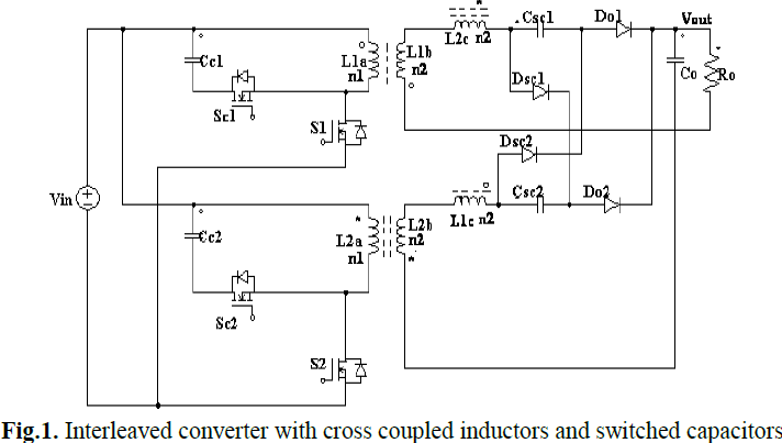
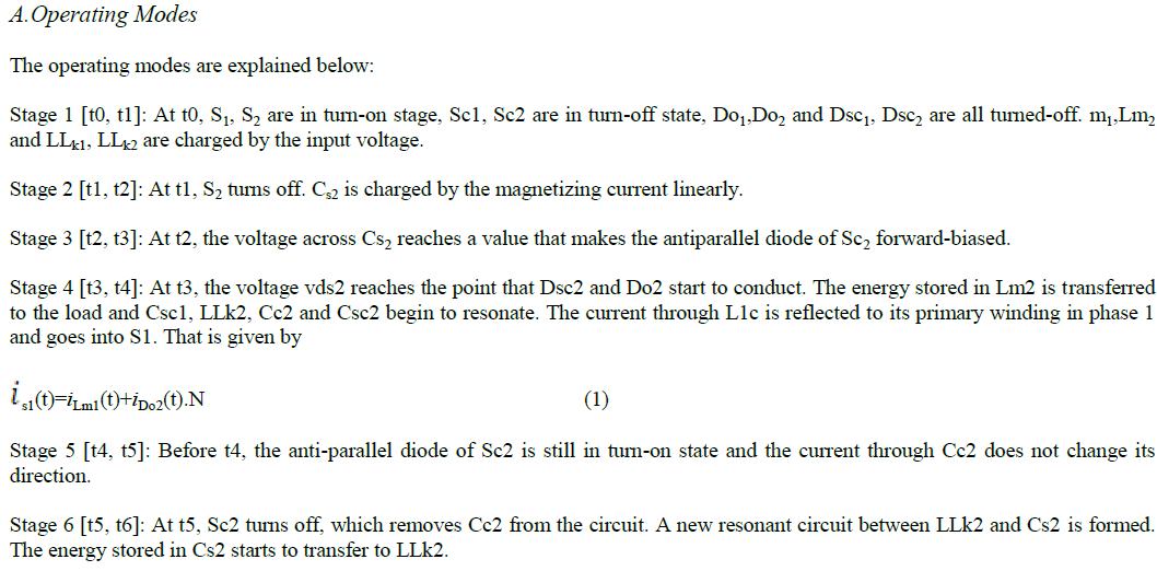
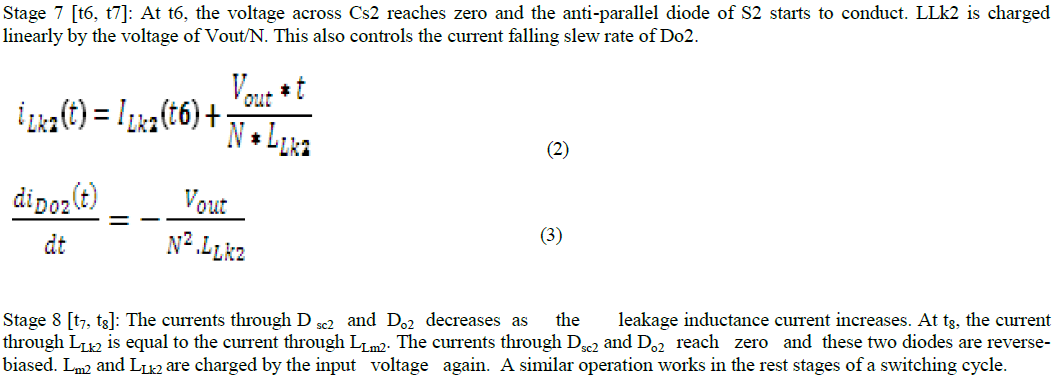
| A normal boost converter converts the DC voltage to a higher DC voltage. Interleaving adds additional benefits such as reduced ripple currents in both input and output circuits. Higher efficiency is realized by splitting the output current into „nâÃâ¬ÃŸ parts, substantially reducing I2R losses and inductor losses. The switched capacitors are included in order to improve the voltage gain of the converter [2]. The advantages of interleaved boost converter are minimized current ripple, increased efficiency, faster transient response, reduced electromagnetic emission and improved reliability [3,4]. The proposed isolated high gain interleaved converter with winding-cross-coupled inductors (WCCIs) and switched capacitors (SCs) is shown in Fig.1.The coupling method of the coupled inductors is marked by “o” and “*”.The second winding couples to the inductor in its phase (L1b versus L1a and L2b versus L2a) and the third winding couples to the inductors in another phase (L1c versus L1a and L1b, L2c versus L2a and L2b). The voltage gain extension circuit, which is composed of the third winding of the coupled inductor, a switched capacitor and a diode, has the advantages of the voltage gain extension and the reduction of the switch voltage stress. The active clamp circuit, which is composed of a power MOSFET and a small capacitor, is inserted to the primary side of each phase to recycle the leakage energy and to absorb the voltage spikes when the main switches turn off. The equivalent circuit model of the proposed converter is demonstrated in where Lm1 and Lm2 are the magnetizing inductors; LLk1 and LLk2 are the leakage inductances; Cs1 and Cs2 are the parallel capacitors of the main switches; Sc1 and Sc2 are the active-clamp switches; Cc1 and Cc2 are the clamp capacitors; S1 and S2 are the main switches; Do1and Do2 are the output diodes; Co is the output capacitor; Csc1 and Csc2 are the switched capacitors; Dsc1 and Dsc2 are the switched diodes. Based on the PWM gate signals of the main switches S1, S2 and the clamp switches Sc1, Sc2, there are 16 stages in a switching period. Due to the symmetry of the converter, only 8 stages are described here. |
 |
 |
 |
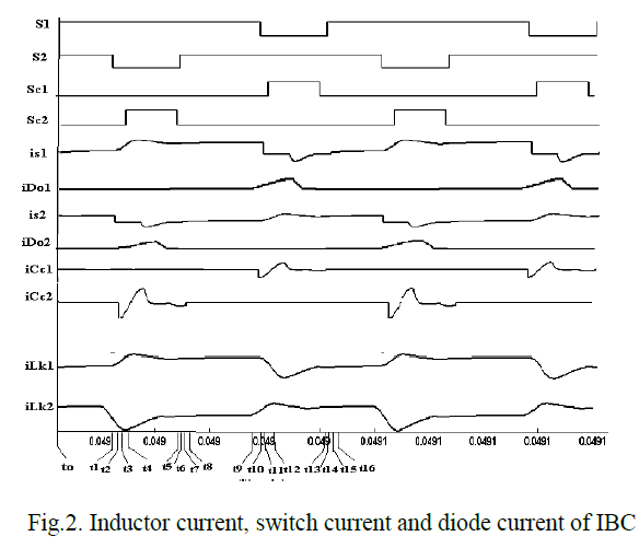
| Figure 3.3 shows the Inductor current, switch current and diode current of high gain Interleaved converter with winding cross coupled inductors and switched capacitors. |
 |
III. DESIGN CONSIDERATIONS |
| The interleaved boost converter design involves the selection of number of phases, the inductors, the output capacitors, the power switches and the output diodes [5,6]. Basically, the design starts with a single boost converter operating at 1/n times the power. |
A. Choosing The Number of Phases |
| This paper utilizes three phases since the ripple content reduces with increase in the number of phases. The ripple reduces to 12% of that of a conventional boost converter. |
B.Selection of duty ratio |
| The decision of the duty cycle is based on the number of phases. This is because depending upon the number of phases, the ripple is minimum at a certain duty ratio. |
C. Selection of Capacitance and Inductance |
 |
| where Vs represents the source voltage (V), D represents the duty ratio (no unit) , F represents frequency (Hz) and Δi L represents the change in inductor current (A). |
D.Selection of Power Devices |
| Power diodes are used for low cut-in voltage, higher reverse leakage current, higher operating frequency. MOSFET is used as a switching device since it is a voltage controlled device, having a high gate circuit impedance. Since it has positive temperature coefficient, secondary breakdown does not occur. |
IV.INTERFACING INTERLEAVED BOOST CONVERTER USING SWITCHED CAPACITORS WITH FUEL CELL SYSTEMS |
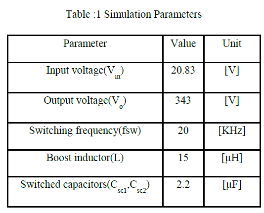
| Fig.3 shows the simulation model of the PEM fuel cell interfaced with Interleaved Boost converter using switched capacitors with cross coupled inductors. The fuel cell output is given to three phase Interleaved Boost converter using switched capacitors with cross coupled inductors. The output is given to the resistive load. The parameters are listed in Table:1. |
 |
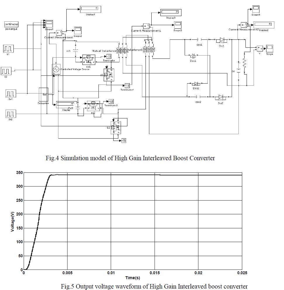 |
| Fig.5 shows the output voltage waveform of interleaved boost converter and it is around 344V. |
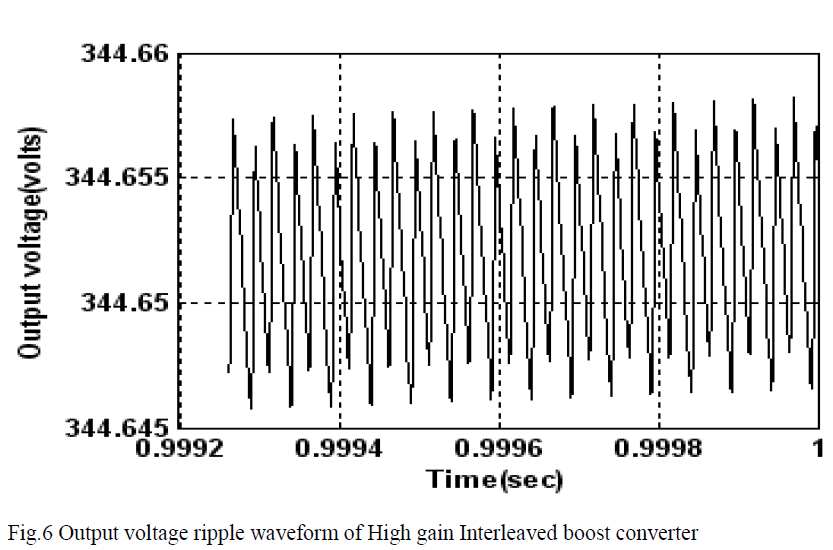 |
| Fig.6 shows the output voltage ripple waveform of interleaved boost and the ripple was found to be 0.0011V. |
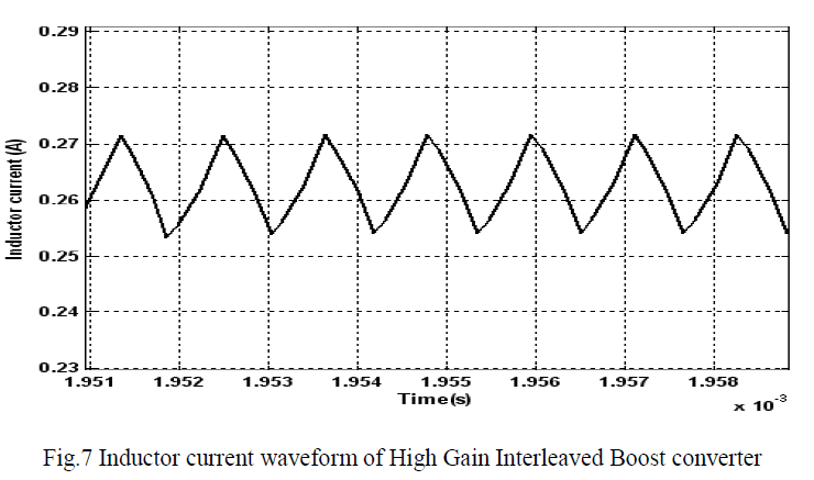 |
| Fig.7 shows the inductor current waveform of high gain interleaved converter and it is found to be 0.07A. The ripple content of high gain interleaved boost converter is compared with the conventional IBC which is shown in Table.2 |
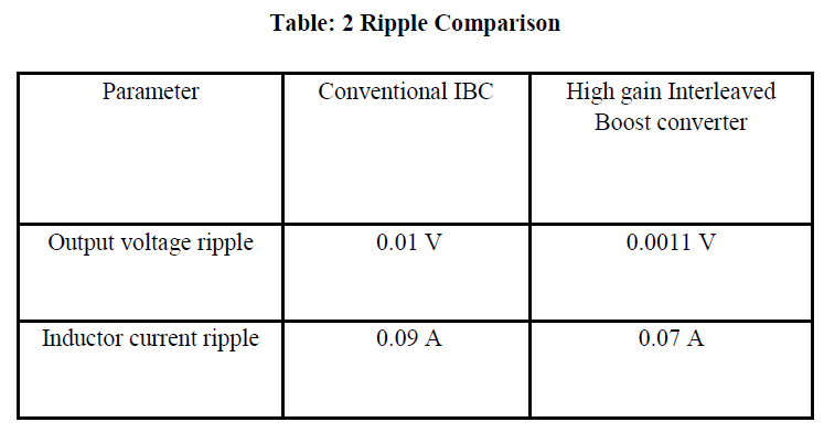 |
| It is found that the ripple content is very less for high gain interleaved converter compared to the conventional IBC.Power loss analysis is carried out for the proposed IBC which includes switching loss, conduction loss and inductor loss [7-9]. The efficiency of the proposed converter circuit is calculated and the maximum efficiency is found out from the efficiency curve. Detailed values of the different power losses of high gain IBC are given in Table 4.6. The total power loss of the interleaved converter with respect to the switch, diode, inductor is observed to be approximately 76 W. |
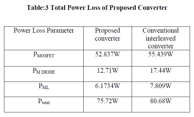 |
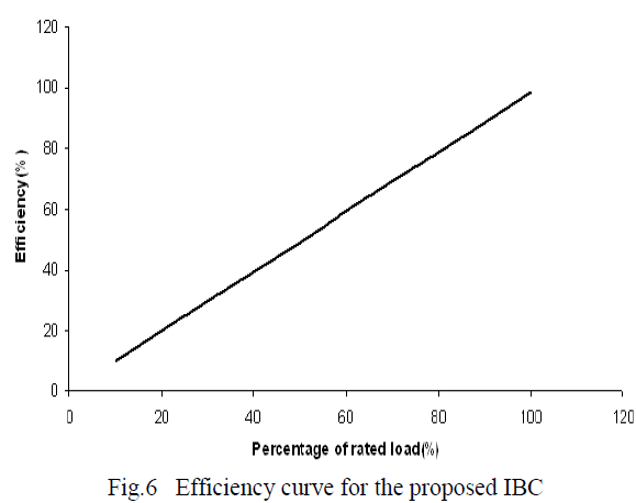
| The calculated power loss of the MOSFET, diode and main inductor of the proposed converter is compared with the power loss of the conventional interleaved converter. It is found that the proposed converter has decreased power loss compared to the conventional interleaved converter. The efficiency of the proposed converter under different loads is sketched in Fig.8 Based on power loss analysis it can be inferred that the conduction losses are minimised by the use of interleaved converter using switched capacitors by means of distribution of the input current. As fast recovery diode has been used, the reverse recovery loss is zero. The total calculated power loss of the converter is estimated to be 76W. Hence it can be seen that the proposed converter gives high efficiency. The maximum efficiency is found to be 98.6% at an input voltage of 20.83V. By interfacing low voltage fuel cells with high gain interleaved converters, the efficiency of the fuel cells can be improved. |
 |
V. EXPERIMENTAL RESULTS |
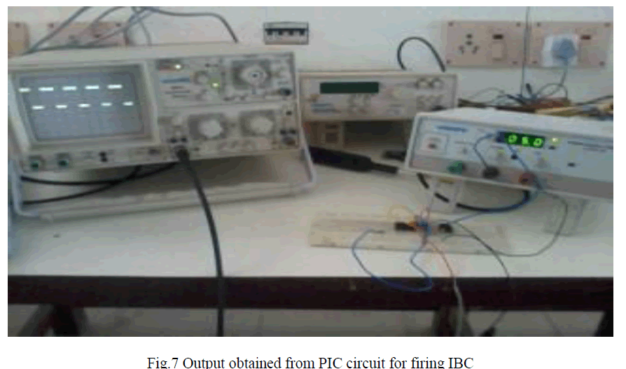
| The experimental part basically consists of power supply circuit, gating circuit and converter circuit. The power supply to the 4N35 optocoupler is given using 12V, 500 mA transformer , Bridge rectifier and a 12V regulator. The gating pulses are generated by PIC controller 18F4550 and given as input to optocoupler. Four MOSFETs IRFP460 are used as switches. Three Cross coupled inductors of 15 μH are used. Two Switched capacitors of 2.2 μF are used to improve the voltage gain. Two Fast Recovery Diodes FR107 are used to reduce reverse recovery losses. Output voltage is taken across a resistive load of 10 Ω. The pulse generation from PIC circuit for firing IBC switches is shown in Fig.7. |
 |
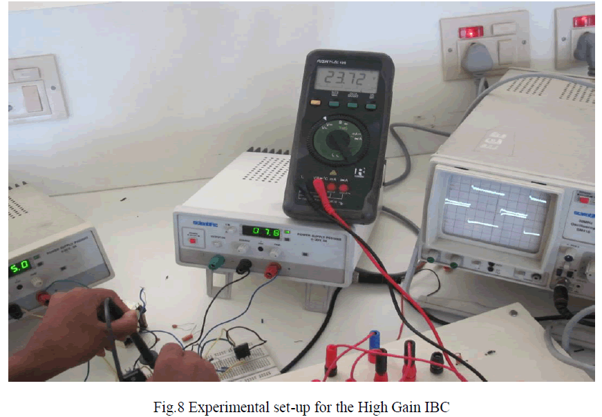 |
| For an input of 7V, an output of 23.72V is obtained for the proposed high gain IBC. It has been observed that the high gain interleaved converter has lower output voltage ripple and inductor current ripple. It serves to be a better topology to be interfaced with fuel cell systems. Also, the power loss of the main devices in the proposed converter is found to be lesser than that of the conventional converter. |
CONCLUSION |
| It is been observed that the high gain interleaved converter has lower output voltage ripple and inductor current ripple interfaced with fuel cell systems. Also, the power loss of the main devices in the proposed converter is found to be lesser than that of the conventional converter. So, maximum efficiency can be achieved by adopting this configuration. The hardware has been implemented for the proposed converter and the results are verified. Therefore, high gain interleaved boost converter is a suitable choice for fuel cell applications. |
References |
|