ISSN ONLINE(2278-8875) PRINT (2320-3765)
ISSN ONLINE(2278-8875) PRINT (2320-3765)
P.Devendra1, Ch.Pavan Kalyan2, K.Alice Mary3, Ch.Saibabu4
|
| Related article at Pubmed, Scholar Google |
Visit for more related articles at International Journal of Advanced Research in Electrical, Electronics and Instrumentation Engineering
The present paper is all about simulation approach for torque ripple minimization of BLDC motor using direct torque control. Brushless DC motors also known as electronically commutated motors where in torque ripples are minimized generally by using current control techniques but the present work mainly concentrate on advanced method for reduction of torque ripples in BLDC motor using the direct torque control. The whole drive system is simulated in MATLAB/SIMULINK based on the system devices, BLDC motor and inverter. The effectiveness of this method is shown through simulation
Keywords |
| Brushless DC Motor, Direct Torque Control, Space Vector Pulse-width Modulation, Torque ripple |
INTRODUCTION |
| The present and future generation is mostly depending on the speed driving systems which have high efficiency and also with a minimum cost. So, for this requirement BLDC motors are very much suitable. Hence the research is also much focusing on BLDC motors. BLDC motors can be classified into two categories as surface mounted permanentmagnet BLDC motors and interior permanent-magnet BLDC motors [1]. As these motors provide commutation externally due to presence of converters, hence the wear and tear is not in the picture. To minimize the torque ripples in these motors trapezoidal back-EMF is needed .It is obtained by employing concentrated winding, skewing the stator slots by one slot pitch. |
| Torque ripples are occurred due to the power electronic commutation, the usage of high frequency switching power devices, imperfections in the stator and the associated control system, the input supply voltage to the motor contains various harmonic components and the pulsating current input due to electronic commutation are also causes for torque ripples [2]. So an efficient controller is required to reduce the harmonics present in the input voltage to the motor and to reduce the pulsating variation of line current to the motor. Optimal torque control schemes for BLDC motors reducing torque ripples and minimizing copper losses have been proposed [3], [4]. Wang et al. proposed a method to minimize the torque ripples generated by non-ideal current waveforms for a BLDC motor without position sensors by adjusting actual phase currents [5]. Lu et al. proposed a torque control method to attenuate torque ripple of BLDC motors with un-ideal back electromotive force (EMF) waveforms [6]. An instantaneous torque controller based on variable structure control in the d –q reference frame was proposed in [7]–[8]. However, although experimental results showed that it was effective in reducing torque ripple, it was only applicable to three-phase BLDC operating in the 180 conduction mode, and not to the more usual 120 conduction mode. In [9], electromagnetic torque pulsations were reduced with a torque controller in which the torque was estimated from the product of the instantaneous back-EMF and current. However, the winding resistance was neglected and the inverter output voltage had to be calculated, which assumed that the back- EMF waveform was known. The simulation approach for torque ripple minimization of BLDC motor using direct torque control is presented in this paper and more details of this work with experimental realization is given in [10] [11] but the present work is highlighted MATLAB/simulink implementation for torque ripple minimization of BLDC motor with direct torque control and results are compared with BLDC motor without direct torque controller. |
II. DIRECT TORQUE CONTROLLER |
| To control the motors variable frequency method is mostly used in industries. In this method to get the good dynamic performance direct torque control is preferred. Based on the measured stator voltage and currents the flux and torque is calculated and a relationship is established between the obtained flux and torque. |
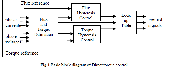
| The fig.1 shows the block diagram of direct torque control [11]. This method involves two stages to estimates the required quantities. In first stage by integrating the stator voltages the stator flux linkage is estimated and the torque is estimated by cross product of obtained stator flux linkage and measured motor currents. In stage two the control signals are obtained by comparing the reference value and estimated values. If any error is produced then the signals are generated based on the demanded values of the torque and stator flux. Thus the dynamic response and torque control is achieved. Hence it is known as one form of the hysteresis control. |
 |
| The electromagnetic torque of a permanent-magnet brushless machine in the synchronously rotating d –q reference frame can be expressed as [1] |
 |
| For applying direct torque control to BLDC motor, the electromagnetic torque is expressed in stationary α-β reference frame using below fig2.[1] |
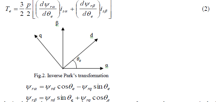 |
| The flux-linkage vectors can be obtained from the measured voltages and currents of stator and rotor respectively. The control signals are obtained by using space vector modulation. |
| In SVM treats the sinusoidal voltage as a constant amplitude vector rotating at constant frequency. A three-phase voltage vector is transformed into a vector in the stationary d-q coordinate frame which represents the spatial vector sum of the three-phase voltage is the basic principle of SVM. |
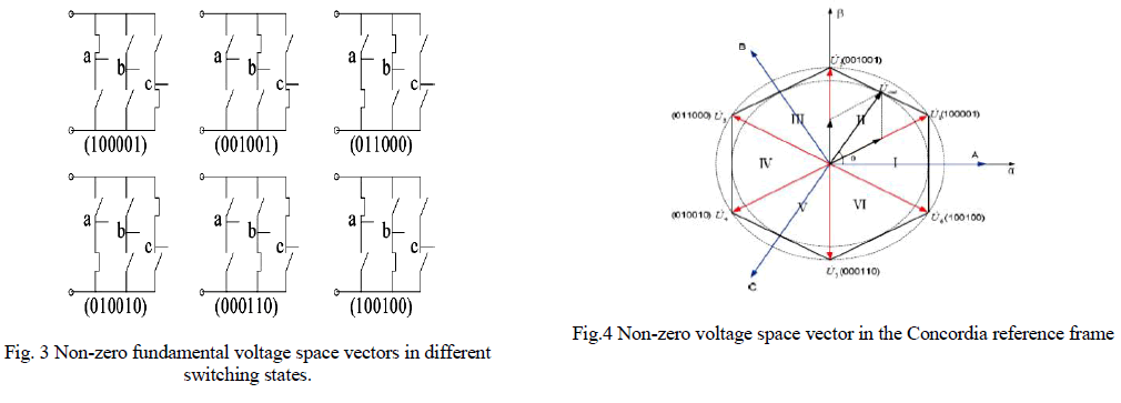
| The 120 conduction mode is generally used in BLDC drives. In it only two phases are conducting in normal period while in commutation another phase also conducting through a freewheeling diode [12]. The inverter switching pulses are represent in six binary digits and each digit represents ON i.e. 1 and OFF i.e. 0 which are voltage space vectors. In this mode both the upper arm and lower arm switching of at the same time, so there is only one zero vector is present and the switching states are shown in Fig. 3. The region of three phase stator axes of the motor is divided into six sectors by non-zero voltage space vector and each sector can be composed of two non-zero voltage space vectors and the zero vectors. |
 |
V. SIMULATION DIAGRAM OF DTC BLDC DRIVE |
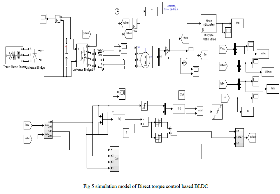
| The basic simulation diagram is shown in Fig.5. The operation is similar to the basic direct torque controller of ac drives expect in calculation of torque. The required flux linkage vectors can be measured using the stator and rotor voltage and currents in terms of stationary reference frame. Finally the electromagnetic torque can be calculated using above formulas. The resultant torque is applied to the switching table which is obtained from speed error through the proportional – integral controller. By using these values the inverter gives the required input voltage to the BLDC motor. |
 |
VI. CURRENT AND FLUX MEASUREMENT IN STATIONARY REFERENCE FRAME |
| The simulation diagram of the block is shown in the fig.6.The three phases current is transformed into stationary α-β reference using above fig.2.The current equations in terms of α-β reference frame can be obtained as below equations |
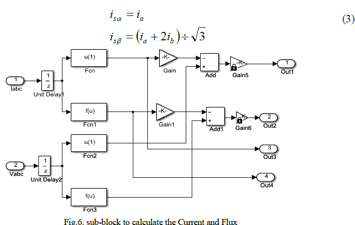 |
| The flux values are calculated from the dc link voltage and transformed into stationary reference frame as shown in below equations |
 |
| The error torque is obtained from speed error which is obtained through speed sensor and is applied to the proportionalintegral controller. The actual torque value is measured by using below equation |
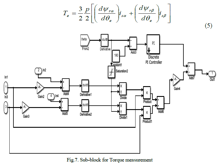 |
VIII. SECTOR SELECTION AND SWITCHING TABLE |
| The required sector is selected based on the flux and torque values and the sector voltages are given in matrix form which are obtained from basic BLDC modes of operation. |
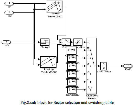 |
| Based on the stator flux linkage and torque status, the switching sequence and pulses are determined and generated respectively. In each sector, if the actual stator flux linkage is the same as the reference stator flux linkage, only one nonzero-voltage space vector and a zero-voltage vector are used to control the torque. In addition, when the actual flux linkage is smaller than the reference value, the nonzero-voltage space vector is used to increase the flux linkage, while when the actual flux linkage is greater than the reference value, the nonzero-voltage space vector is used to decrease the stator flux linkage. The switching table is shown in table 1. |
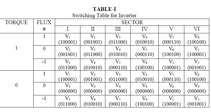 |
IX. SIMULATION RESULTS |
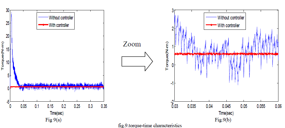
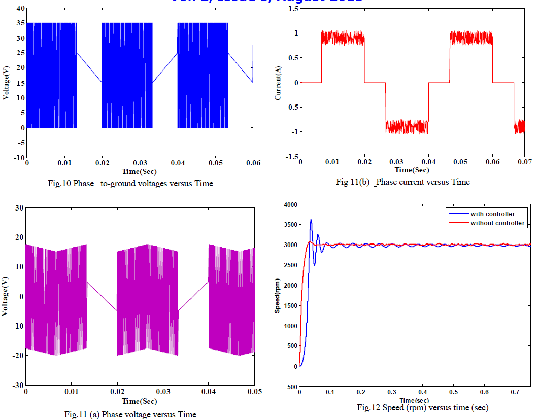
| To show the performance of direct torque control on BLDC drive, the obtained results are comparing with conventional BLDC drive. The simulated torque characteristics of BLDC drive system without and with DTC controller are compared in fig 9 under the same operating condition. The fig 9(a) shows the normal position and fig 9(b) shows that its zoom in position for compares the clear view. The torque time characteristics show that the direct torque control has good dynamic performance and reduced the torque ripples compared to the ordinary speed control. The phase to ground voltage is shown in fig10. The voltage maintains constant maximum value at every cycle. |
 |
| The phase to phase voltage and currents are shown in fig 11(a) and 11(b) respectively. The phase current waveform is shown only one phase of the motor. The currents are in square waveforms but exhibits ripples at the steady state. |
| The speed –time characteristics shown in fig .12.The results shows that the ordinary speed control will not get the steady state till the end while direct torque control is reached stable position after sometime. |
 |
[X] CONCLUSION |
| Torque ripple minimization of BLDC motor using direct torque control has been implemented successfully and it is compared with ordinary speed control technique. The effectiveness of the proposed work is shown through in simulation using MATLAB/ simulink. |
| The obtained results show the good dynamic performance and reduced torque ripples in BLDC motor. The above results depict that the direct torque control is capable of controlling the torque instantaneously. |
 |
References |
|