ISSN ONLINE(2278-8875) PRINT (2320-3765)
ISSN ONLINE(2278-8875) PRINT (2320-3765)
| S. Yang Assistant professor, Department of EE and CS, Alabama A & M University, Huntsville, Alabama, USA |
| Related article at Pubmed, Scholar Google |
Visit for more related articles at International Journal of Advanced Research in Electrical, Electronics and Instrumentation Engineering
Keywords |
| Bandstop Filter, Open Stub, Optimum Bandstop Filter. |
INTRODUCTION |
| Microstrip bandstop filters are being widely used in microwave systems. Various techniques have been developed to design and synthesis these BSFs [1]. Dual-band bandstop filters are highly desired in many applications for their two separate stopbands at two different frequencies. Conventionally, a dual-band BSF can be obtained by cascading two different BSFs. The side effects are the high insertion loss in the passband and increased circuit size. In this paper, a dual-band BSF is formed by combining a conventional two open stubs BSF and an optimum BSF. By inserting an optimum BSF between the two open stubs of a conventional BSF, one can obtain a second stopband without increasing the overall circuit size much. The proposed BSF is simulated on Sonnet Suite software. |
II. RELATED WORK |
| A conventional open stubs BSF can be formed by mounting open stubs onto a microstrip. The length of the open stubs and the separation between the neighboring stubs are a quarter of the wavelength at the midband frequency [2, 3]. Varies methods have been proposed to form dual-band BSFs. The dual stopbands can be obtained through frequencyvariable transformation to the lowpass prototype [4] and cul-de-sac configuration [5], and the application of right/lefthanded metamaterials [6], parallel open stubs at different lengths [7] and dual mode ring oscillators [8]. To reduce the size of dual-band BSFs is a hot research topic. Stepped impedance resonators (SIR) [9], split ring resonators [10], and the combination of SIR transmission line and defected ground structure (DGS) [11] have been used to realize the desired dual stopbands with circuit size reduction. |
III. FILTER LAYOUTS AND SIMULATION RESULTS |
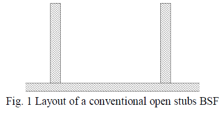
| Fig.1 shows the configuration of a conventional open stub BSF. The length of the two stubs and the separation between the two stubs are a quarter of the wavelength at the midband frequency. The substrate material is Rogers TMM10i with a relative dielectric constant of 9.8 and a loss tangent of 0.002. The thickness of the substrate is 1.27 mm. The whole backside of the substrate is the ground plane. The width of the feed line and the open stubs is 1.2 mm, which gives a characteristic impedance of 50 Ohm. The two open stubs are 11.90 mm long and the separation between the centers of the two open stubs is also 11.90 mm. |
 |
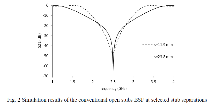
| This conventional BSF is simulated on Sonnet Suite 14.52 at two different stub separations 11.90mm and 23.8 mm, and the simulated insertion losses are shown together in Fig. 2. The midband frequency is very close to 2.5 GHz at these two stub separations, although the stopband attenuation profiles are different. |
 |
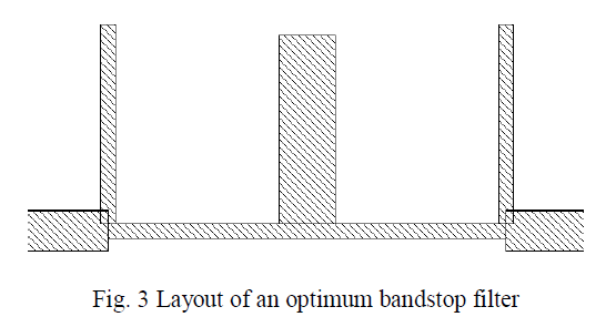
| An optimum BSF filter can provide very low insertion loss and very low reflection in the passband while keeping very deep rejection in the stopband. Such an optimum BSF, with three open stubs, has a fractional bandwidth of 0.8 and a midband frequency of 4.9 GHz is designed. The passband return loss is set at -20 dB. Normalized element values can be found in tables [1] as g1=g3=0.67986, g2=1.17702, and J12=J23=0.67677. Then characteristic impedances of these quarter wavelength stubs and the two connections between these three stubs are calculated [1] as Z1=Z3=73.54 Ohms, Z2=42.48 Ohms and Z12=Z23=73.88 Ohms. This BSF is built on the same substrate mentioned early. The line width and length of each segment are calculated on AppCAD software directly. The lengths of the three open stubs are set to a quarter of the wavelengths for 0.47 mm and 1.7 mm wide microstrip lines at 4.9 GHz. The distance between the centers of the neighboring open stubs is set to a quarter of the wavelengths for a 0.46 mm wide microstrip at 4.9 GHz. The layout of this optimum BSF is shown in Fig. 3. |
 |
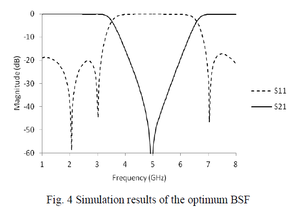
| This optimum BSF is simulated on Sonnet Suite 14.52, and the simulation results are shown in Figure 4. It has a stopband around 4.9 GHz. The deepest rejection at 4.9 GHz is more than -60 dB. In the passbands (lower than 3.0 GHz and higher than 7.0 GHz), the return loss is low. So that this optimum BSF’s characteristic impedance is close to 50 Ohm in these two passbands. |
 |
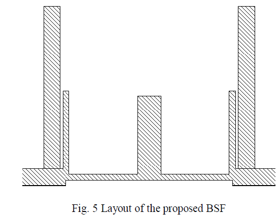
| The proposed BSF is a combination of the conventional two open stubs BSF and the optimum BSF. The optimum BSF is inserted between the two open stubs of the conventional BSF. This optimum BSF works like a 50 Ohm microstrip connection line beyond its stopband. Simulations can show that electrical length of this optimum BSF is about 180 degrees (equivalent to half wavelength) at 2.5 GHz. Simulation results in Fig. 2 show that the conventional BSF still keeps its stopband at 2.5 GHz with a half wavelength stub separation. Layout of the proposed BSF is shown in Fig. 5. The small separation between the open stub of the conventional BSF and the open stub in the optimum BSF is set to 0.2 mm. |
 |
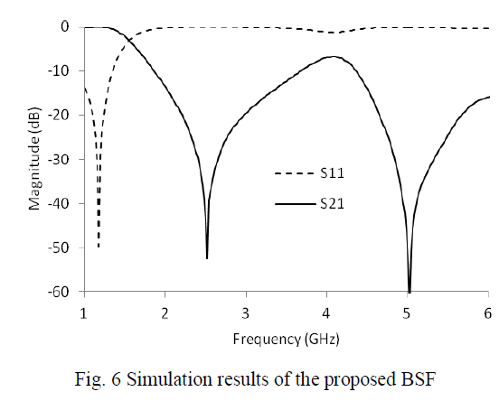
| The proposed BSF is simulated on Sonnet Suite, and the simulation results are shown in Fig. 6. The first stopband generated from the two longer open stubs is still around 2.52 GHz. The second stopband from the optimum bandstop filter is around 5.02 GHz. The attenuation at 2.52 GHz is more than -50 dB, and the attenuation at 5.02 GHz is more than -60 dB. This proposed BSF generates these two stopbands without increasing the overall circuit size much. |
 |
IV. CONCLUSIONS |
| An optimum BSF is inserted between the two open stubs of a conventional BSF to form a compact dual-band BSF. The proposed BSF is simulated on Sonnet Suite software. Simulation results show the formation of two stopbands around 2.52 GHz and 5.02 GHz. |
ACKNOWLEDGMENT |
| The author would like to thank Dr. Montgomery for his financial help, Dr. Scott for his help to install Sonnet Suite software, and Dr. Heidary for his microwave network analyzer. |
References |
|