ISSN ONLINE(2278-8875) PRINT (2320-3765)
ISSN ONLINE(2278-8875) PRINT (2320-3765)
Dr.R.Seyezhai 1 , P.Chitra 2
|
| Related article at Pubmed, Scholar Google |
Visit for more related articles at International Journal of Advanced Research in Electrical, Electronics and Instrumentation Engineering
This paper presents the simulation of an Interleaved LLC Resonant DC-DC converter for renewable energy sources. The proposed topology reduces the voltage and current stress of the components, increases the step down conversion efficiency and reduces the component count compared to the conventional dual LLC converters. Zero voltage switching (ZVS) is applied for the main switches and zero current switching (ZCS) for the resonant diodes to reduce the switching losses. The basic design of the proposed converter is discussed in this paper. Simulation studies are carried out in MATLAB. The results are verified.
Keywords |
| Interleaved LLC, Zero Voltage Switching, Zero Current Switching, Renewable energy systems |
INTRODUCTION |
| Nowadays power capacity and high conversion efficiency are essential for renewable power generation systems. For medium and high power applications full bridge and half bridge converters are frequently adopted. Variable duty ratio and modulating frequency are the control measures of these full / half bridge-type converters. Active-clamping converters [1], asymmetric half-bridge converters, and phase shift pulse width modulation converters performing zero voltage switching (ZVS) or zero current switching (ZCS) with lower switching losses and reach higher efficiency by duty ratio control. However, at wide input voltage range and different load conditions these converters are difficult to achieve ZVS resonant phenomenon [2-3]. At high frequency control, which effectively extend operating range for either ZVS or ZCS transient at various load conditions many full / half bridge resonant converters are operated. There are two main disadvantages for the pure series and parallel resonant converters. In series resonant converters at no-load conditions the output voltage cannot be controlled properly and in parallel resonant converters the circulating energy in resonant tanks is too high thereby the circuit efficiency is reduced [3-5]. The LLC resonant converter has many advantages than series and parallel resonant converters. It has high conversion efficiency and narrow frequency variation. For wide input voltage range and variable load conditions the power switches can be turned on at ZVS and the rectifier diodes can also be turned off at ZCS [5-6]. |
| For higher power applications, dual converters are proposed for its input structure either in series or parallel connection with interleaved switching scheme. Some researchers focused on developing multi-resonant-tank converter for decreasing current and voltage stress on components [6-9]. These converters are used to double output power, reduce output current ripple and decrease stress on components. However, the parts count and size are getting increased. Large power capability can be attained by connecting two-phase interleaved LLC converters in series or in parallel [10]. Due to the input parallel or series connection these solutions reduce the current or voltage stress on components at primary side. Thus, to reduce the size and cost but still to transfer the same power, a novel LLC converter with parallel-input parallel-output resonant tank is proposed in this paper. |
II.INTERLEAVED LLC |
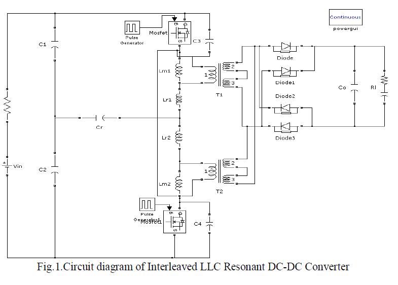
| LLC resonant converters exhibit a large voltage ripple on output filter capacitor because of the rectified sine-wave current injected through the transformer secondary windings. In order to reduce the capacitor size and/or the steadystate output voltage ripple, the interleaved approach can be profitably applied. The parameters of dual resonant tanks are identical. The duty cycle of gate signal vG1 and vG2 are both approximate 50 % complementary to each other. The active switches and output rectifiers reach ZVS and ZCS in the dead time zone. [11] .In Figure 1 the interleaved LLC resonant DC-DC converter is depicted: two identical modules are parallel connected and switched at the same frequency but with 180 degrees phase-shift of their driving signals. |
 |
III.MODES OF OPERATION |
 |
 |
IV.DESIGN EQUATIONS |
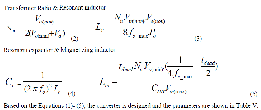
| The design equations for the resonant frequency , transformer turns ratio, resonant inductor and resonant capacitor are shown as below: |
| The two resonant frequencies are, |
 |
 |
V.SIMULATION PARAMETERS |
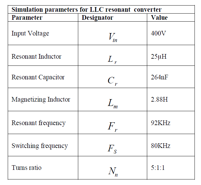 |
VI. RESULTS AND DISCUSSION |
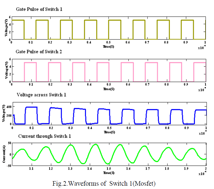
| In Fig.2.gating pulses of two switches are shown. Also the voltage and current waveforms are depicted for switch 1. Voltage and current of switch 1 are obtained as 400V ,50A respectively |
 |
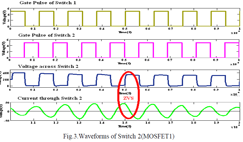
| Voltage and current waveforms of switch 2 are shown in Fig.3. They are obtained as 400V, 50A respectively. Here the achievement of ZVS is shown. |
 |
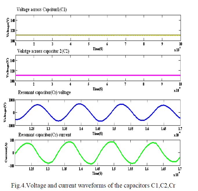
| In Fig.4.Voltage across capacitor 1, capacitor 2, resonant capacitor and current through the resonant capacitor are shown. Voltage across the capacitors 1 and 2 is obtained as 110V. It is clear from the figure that the voltage and current of resonant capacitor are in phase |
 |
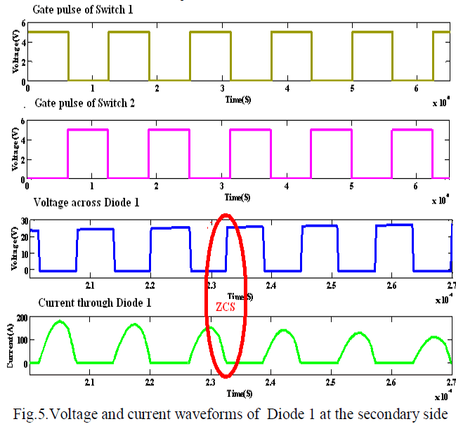
| In Fig.5.voltage and current waveforms of secondary side diode are shown. Here ZCS is achieved. |
 |
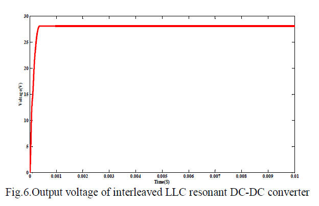
| In Fig.6.output voltage waveform is shown. For the input of 400V the output is obtained as 28V. |
 |
VII. CONCLUSION |
| Simulation of an Interleaved LLC Resonant DC-DC converter is presented in this paper. The proposed converter reduces the current and voltage stress on the components and for an input of of 400V, the output obtained is 28V. By soft switching, the losses are reduced and the component count of the proposed LLC results in reduced size compared to the dual LLC topology. |
References |
|