International Journal of Advanced Research in Electrical, Electronics and Instrumentation Engineering
ISSN ONLINE(2278-8875) PRINT (2320-3765)
ISSN ONLINE(2278-8875) PRINT (2320-3765)
Ramakant Shukla1, Rahul Agrawal2
|
| Related article at Pubmed, Scholar Google |
Visit for more related articles at International Journal of Advanced Research in Electrical, Electronics and Instrumentation Engineering
It is not possible to connect power semiconductor switch directly at medium and high voltage level. This introduced a new unit of inverters as a result of applying higher voltage levels, which can be called as multilevel inverters. Multilevel inverters are synthesizing close to sinusoidal voltage from some levels of DC voltages. Multilevel inverters synthesize the stair – case voltage waveform with some lower harmonic content. The output voltages from inverters have reduced harmonic distortions and good quality of waveforms. Because when used this inverter THD content in voltage waveform is very significant it affects the performance of load. This article deals with study and analysis of a single phase multilevel inverter with various levels. By using Matlab different multilevel inverter models are simulated and get an output voltage waveform and THD.
Keywords |
| Multilevel inverter, Simulink, THD |
INTRODUCTION |
| In recent years, the need for a high power apparatus has been derived from numerous industrial applications. Multilevel inverters have been attracting because of increased power ratings, better harmonic performance and optimized electromagnetic interference (EMI) emission that can be archived with multiple DC levels that are a synthesis of the output voltage waveform. Medium voltage grids, motor drives and utility applications are a few examples, where it is required to convert DC power into AC power. As a consequence, several multilevel power converter structures have been presented. A multilevel inverter is a device that synthesizes near sinusoidal voltage from various DC voltages. Multilevel converters not only reach high power ratings, but also enable the utilization of renewable energy sources like photovoltaic, wind, fuel cell, etc. Multilevel converters use more than one DC voltage source, battery or capacitors, to bring forth more than one layer of output voltage. Multilevel inverters have been under research and development for more than three decades and have established successful industrial applications. |
| The general concept involves using a higher number of semiconductor switches to execute the power transition in small voltage steps. |
| The main features of a multi-level structure are as follows:- |
| 1. Without increasing the rating of an individual device, the increment of output power and voltage is possible. |
| 2. The disservices of the switches do not run into any voltage sharing problems. This makes multi-level inverters easy to be used for applications involving high power like bulky motor drivers and utility supplies. |
| 3. Multilevel inverters have high efficiency because it can be switched at low frequency. They have the higher voltage capability. |
| 4. Multilevel converters can reduce (dv / dt) to conquer the motor failure problem and EMI problems. |
| 5. No clamping diodes present as in NPC. |
| 6. No voltage balancing capacitors present in FC. |
| 7. With the increase in the number of the level, the staircase waveform approximates to a sinusoid. |
| 8. No transformer required as in multi-pulse inverters [1, 2]. |
| The new features are compatible to use in reactive power compensation which makes inverter to produce a high power, high voltage utility with multilevel structures. The unique structures of multilevel voltage source inverters permit them to approach high voltages with low harmonics instead the use of transformers. There are different power converters which used in the circuit there is the issue of waveform quality is one the important concern and it can be addressed in many ways. Waveforms are filtered using capacitors and inductors, practically. Filtering is done on primary and secondary winding or to both of them if the transformer is used. To make the output waveform qualitative, low pass filters are often added in the circuit. The inverter is the solution of what kinds of problems which related quality of output waveform without losing its efficiency [2]. |
| A three level inverter produces an output voltage level of 0, +Vdc and - Vdc. A three level inverter limits at high frequency because of switching losses and device rating constraints. Three-level converter started the term multi level converter. |
| Subsequently, several multilevel topologies have been developed. In 1981, the Neutral Point Clamped (NPC) diode) inverter schemes were proposed (A. Nabae, I. Takahashi, and H. Akagi) [3], they are also called as Clamped Multilevel inverter (DCMLI. In 1992, Flying Capacitor Multilevel inverters (FCMI), (T.A. Meynard and H. Foch) and in 1996, Cascaded Multilevel inverters (CMI) were proposed (J. S. Lai and F. Z. Peng). Although the CMI was invented earlier, its application did not prevail until the mid 1990s [4]. The advantages of cascaded multilevel inverters were prominent for motor drives and utility applications. The cascaded inverter increased the demand of medium-voltage high-power inverters. L.M. Tolbert (1999) proposed novel multilevel inverter carrier based pulse width modulation methods, namely multicarrier and phase shifted carrier pulse width modulation. Multilevel inverters are applicable to industrial medium voltage motor drives, utility interface for renewable energy systems, flexible alternate current transmission system and traction drive systems. |
| One more alternative for a multilevel inverter is the cascaded multilevel inverter or series H-bridge inverter. The series H-bridge inverter appeared in 1975. Mahesh Manivanna and Rama Redd proposed a topology for cascade H-Bridge multilevel inverter. This topology consist eight switches, eight diodes and two DC sources [5]. The Cascaded multilevel inverter was not fully realized until two researchers, Lai and Peng. They patented it and presented its various advantages in 1997. New inverter topology is introduced here, which is uses separate dc sources [6]. |
II. CASCADE H BRIDGE MULTILEVEL INVERTER |
| One more alternative for a multilevel inverter is the cascaded multilevel inverter or series H-bridge inverter. The series H-bridge inverter appeared in 1975 [7]. The Cascaded multilevel inverter was not fully realized until two researchers, Lai and Peng. They patented it and presented its various advantages in 1997. New inverter topology is introduced here, which is uses separate dc sources [8]. Since then, the CMI has been utilized in a wide range of applications. With its modularity and flexibility, the CMI shows superiority in high-power applications, especially shunt and series connected FACTS controllers. The CMI output voltage waveforms are synthesized by combining many remote voltage levels. Fig. 2.3 shows the three-level cascade H bridge multilevel inverters respectively. |
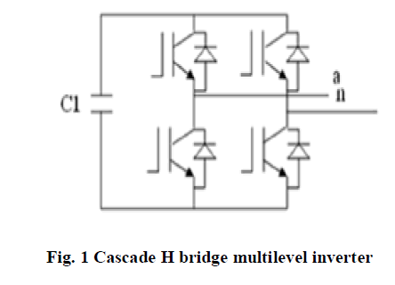 |
| Each level of inverter produces three different voltage outputs namely, +Vdc, 0, and –Vdc by connecting ac output with the dc supply using dissimilar combinations of the four switches, S1, S2, S3, S4. To taken +Vdc, switches S1 and S4 are turned on, and –Vdc can be taken by turning on switches S2 and S3. Turning on S1 and S2 or S3 and S4, the voltage of output becomes 0. The ac outputs of all full-bridge inverter levels are connected in series to get the synthesized voltage waveform as the sum of the inverter outputs. |
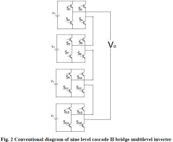 |
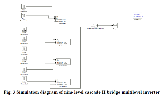
| Nine level cascade H bridge multilevel inverters are shown in fig. 2 in the circuit for DC source and sixteen IGBT are used for switching purposes. The Simulink model of nine level cascade H bridge multilevel inverter is shown in fig. 3. It consist eight pulse generators, four subsystems, one voltage measurement, one scope and one power GUI. |
 |
| Each part of dc source (SDCS) is connected to a single-phase full-bridge or H-bridge inverter. The magnitude of the ac output phase, the voltage is the sum of the voltages obtained by H-bridges. The output voltage of Four H Bridges is nine levels (0V, 3V, 6V, 9V, 12V, -3V, -6V, -9V, -12V). |
III. FOURIER SERIES AND HARMONICS ELIMINATION THEORY |
| The Fourier expression of the multilevel output voltage can be gained by putting Fourier theory to the output voltage waveform of multilevel converters, as (1). If in the multilevel converter, the DC voltages are equal, the equation for the basic frequency switching control method can be represented as: |
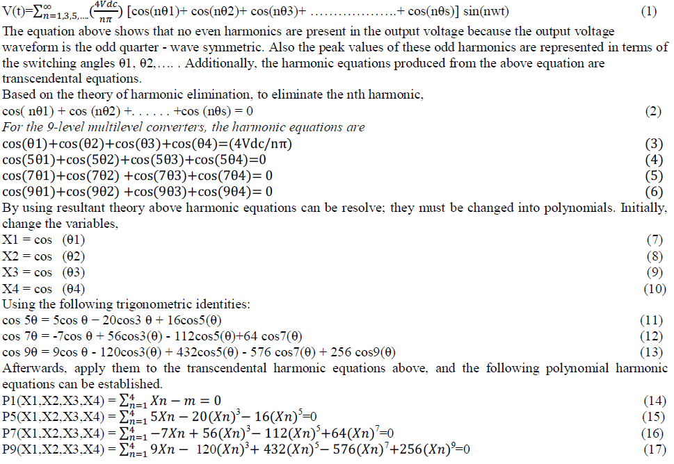 |
IV. RESULT |
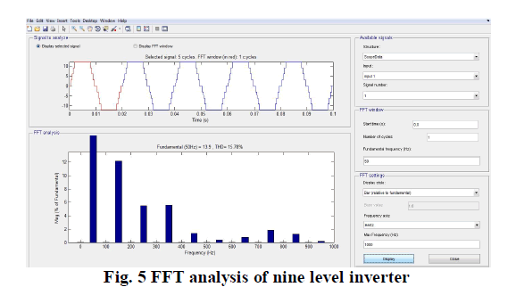
| Simulink model of nine level cascade H bridge multilevel inverter is shown in fig. 3. The output voltage waveform associated with the nine level cascade H bridge multilevel inverter is shown in fig. 4 and fig. 5 represents the FFT analysis of the same. |
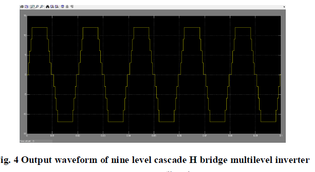 |
| From the output voltage waveform it is clear that the nine levels are: |
| 0V, 3V, 6V, 9V, 12V, -3V, -6V, -9V, -12V |
| The THD of the model is 28.81% |
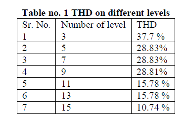
| Similarly simulation model for 5, 7, 11 and above up to 17 level are simulated in Matlab and following results are obtain. |
 |
| Similarly simulation model for 5, 7, 11 and above up to 17 level are simulated in Matlab and following results are obtain. |
 |
CONCLUSION |
| This paper studied related to simulation of cascade H bridge multilevel inverter and reducing harmonic by cascading H bridges. Multilevel inverter is simulated using MATLAB software. And THD analysis is done using the FFT tool of MATLAB software. Firing angles are calculated using function FSOLVE in MATLAB. |
| It is clear from table no. 1 THD of multilevel inverter is reduced by cascading H bridges. |
References |
|