ISSN ONLINE(2278-8875) PRINT (2320-3765)
ISSN ONLINE(2278-8875) PRINT (2320-3765)
Cicily Antony T1, Beena M Varghese2, Anish Gopinath3
|
| Related article at Pubmed, Scholar Google |
Visit for more related articles at International Journal of Advanced Research in Electrical, Electronics and Instrumentation Engineering
BLDC motor is a type of DC motor, which commutate electronically instead of using brushes.To impact rotation to this motor, commutation schemes are necessary. The paper presents a commutation scheme called quasi sinusoidal commutation which takes the advantage of conventional trapezoidal and sinusoidal commutation algorithm. The proposed logic reduces the torque ripple associated with ten step commutation and switching loss associated with sinusoidal commutation logic. The paper mainly concentrated on mathematical modelling offive phase BLDC motor with quasi sinusoidal commutation logic. The simulation of proposed commutation scheme was carried out in MATLAB/SIMULINK and the simulated results are presented to demonstrate the effectiveness of proposed commutation. Simulation model of the controllerand BLDC drive are also presented.
Keywords |
| five phase BLDC motor, quasi-sinusoidal commutation, five legged inverter, Hall sensor |
INTRODUCTION |
| The permanent magnet brushless DC motor is a synchronous motor with permanent magnet as rotor and wound core as stator. This motor starts to attract the industrial world from early 1970’s due to their inherent advantages of higher speed range, less maintenance, higher efficiency, noiseless operation and longer life [1]-[2]. Even though DC motors possess good control characteristics, their performance and applications are inhibited due to sparking and commutation problems [3]. The design of BLDC motor eliminates the requirement of brushes by using electronics. With the advancement of solid state devices and the availability of rare earth alloy permanent magnet, the BLDC motor starts to penetrate the attention of variable speed drives. Most of the BLDC motors available in market are three phase system and with the potential benefits of phase order higher than three now researches are going on multiphase system. |
| The multiphase system is a system with numerous numbers of windings or circuits. The winding arrangement and the construction of multiphase motor are similar to that of a three phase motor except the number of windings arranged in the stator. Multiphase BLDC motor find more importance in medium and high power drives because of their inherent advantages of high reliability, fault tolerant capability, reduced current per phase, reduced amplitude and increased frequency of torque pulsation over the convention three phase BLDC motor [4]. For aerospace, military applications, fault tolerant capability is an important consideration. In multiphase system, the motor can operate normally even if one or more phases get failed. For the proper operation of BLDC motor, a suitable commutation sequence and a power electronic converter is necessary. For BLDC motors, the type of commutation scheme adopted determines the torque ripple at the output which attributes to one of the major losses [5] |
| The conventional methods of implementing commutation for a BLDC motor are trapezoidal commutation and sinusoidal commutation [5], [6]. The trapezoidal commutationoffers a simple implementation with reduced switching loss, but with increased torque ripple. The implementation of trapezoidal commutation can be done with the rotor position information available from the hall sensors.Sinusoidal commutation scheme eliminates the torque ripple and commutation spikes associated with trapezoidal commutation but its implementation requires accurate sensing of the rotor position [6]-[10]. |
| The paper presents a commutation logic called quasi sinusoidal commutation for a five phase BLDC motor. The proposed commutation logic takes the advantage of both ten step and sinusoidal commutation scheme. The presented commutation scheme has the advantages like simpler implementation, reduced switching and lesser torque ripple. The mathematical modelling of five phase BLDC motor drive with quasi sinusoidal commutation was carried out in MATLAB/SIMULINK and the results are presented to demonstrate the effectiveness of system. |
PROPOSED COMMUTATION SCHEME |
| Brushless DC motor requires electronic commutation for the direction control of current through the windings. The conventional commutation schemes used to impact rotation to a BLDC motor are trapezoidal commutation and sinusoidal commutation. In trapezoidal commutation two phases are conducting at a time and the remaining one phase will be in non-energized condition. This method can be implemented with the information achieved from the hall sensors and with reduced switching loss. But the inherent disadvantage associated with this method is the higher torque ripple in comparison to sinusoidal commutation. In Sinusoidally commutated BLDC motor, controllers attempt to drive the three phase motor windings with three currents that vary smoothly and sinusoidally. This eliminates torque ripple and commutation spikes associated with trapezoidal commutation [5]. This control method provides better performance and efficiency at lower speed. The main drawback associated with this method is the requirement of highly precise encoders for position sensing and higher switching loss. |
| The proposed commutation scheme nearly resembles to a sinusoidal commutation and hence the name quasi- sinusoidal commutation. In this commutation scheme all the phases are conducting at a time as like a sinusoidal commutation but with reduced switching, that is only one phase is switched at a time and all other phases are either clamped to Vcc (1) or GND(0). The implementation of presented commutation scheme is simple as like ten step commutation and also it provides reduced switching loss and reduced torque ripple. |
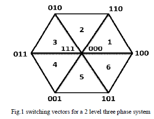 |
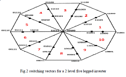
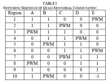
| Fig.1 shows the switching vector for a two level inverter. It contains eight switching vectors, among them six are active vectors and two are zero vectors. The active vectors are located at the vertices of hexagon. 111 and 000 are the two zero vectors, in which all the upper switches or lower switches of the inverter are closed. The hexagon is divided into six regions marked 1 - 6.At any instant the reference vectors can locate any of the six region and the reference vector is approximated by switching the vectors located closest to the reference space vector [6], [10]. Consider, the reference space vector is located at region 1, the reference vector is approximated by switching the vectors 000 - 101 - 100 -111. If only active vectors are considered then the reference vector is approximated by switching 101 and 100. It may be observed that among the vectors 101 and 100, A phase remains clamped to 1, B phase remains clamped to 0 and the C phase will switch based on PWM. This logic in a three phase system can be extended to a five phase system. In a five phase system it contains thirty two switching vectors [00000-11111] as shown in Fig.2. Among them thirty are active vectors and two are zero vectors. The entire decagon can be divided into30 regions. The reference vectors can locate at any of the thirty regions. Here only last largest ten outer regions are considered for developing the switching sequence. Consider the reference vector is at region 5.In the present work only the active vectors are considered and hence the reference vector can be approximated by switching 01110-00110. It may be observed that, out of five phases the phase A and phase E are clamped to 0 ,phase C and phase D are clamped to 1 and the phase B alone switch based on PWM. This reduces the switching.The region in which reference vectors are located can be determined with the rotor position information available from the hall sensors mounted on stator winding. Table 1 shows the region and the corresponding switching sequence developed. |
 |
 |
| The proposed commutation scheme provides nearly sinusoidal current waveform. This commutation scheme offers simplicity in implementation with reduced switching loss and reduced torque ripple. |
MATHEMATICAL MODELLING OF FIVE PHASE BLDC MOTOR |
| The model of five phase BLDC motor drive was developedin MATLAB/SIMULINK using the classical modelling equation [7]-[10] and the simulation of proposed quasi sinusoidal commutation scheme was carried out. The equations are derived from the equivalent circuit of BLDC motor.The current through each phase winding was modelled using the equation (1). |
| where i = A, B, C, D and E |
| The instantaneous phase voltage in BLDC motor is given in equation (2)-(6)where,ïÿýïÿý is the rotor electrical position. |
 |
 |
| The torque developed by the motor is given in the equation (7) |
SIMULATION RESULTS |
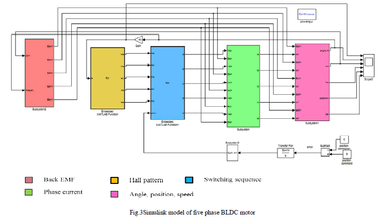
| Fig. 3 shows the Simulink model of five phase BLDC motor. The simulation parameters used are L=0.7mH and R=0.7 ohm.The hall sensor pattern and the corresponding switching sequence developed for a five BLDC motor was entered using embedded MATLAB functions. The duration of conduction of each switch was controlled by a PWM signal of 10 KHz frequency, generated by comparing the command signal with triangular waveform. |
 |
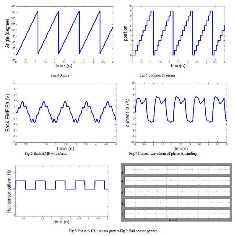
| Fig. 4 represents the angle of rotation of BLDC motor. The angle obtained is compared with 360 degree and whenever the angle is greater than 360 degree the integrator is reset to initial value. Fig.5 represents the position of rotor. If rotor moves from 0 to 360 degree, the position is 1 and for the next 36 degree movement the position is 2 and similarly for other angles. The back EMF waveform of presented topology has nearly sinusoidal shape as shown in Fig.6 and Fig.7 represents the current through phase A winding of motor. Here the current waveform has nearly sinusoidal shape. The hall sensor pattern of phase A is given in Fig.8. The hallsensors are mounted on stator winding and in 72 degree apart from each other. Fig.9 shows the hall sensor pattern of all the five phases in which all are displaced by 72 degree. |
 |
CONCLUSION |
| The mathematical model of five phase BLDC motor was developed and the simulation of proposed quasi sinusoidal commutation algorithm was carried out in MATLAB/SIMULINK. The hall sensor pattern and the corresponding switching sequence at which the rotor rotates are determined and the corresponding waveforms of current through each phase as well as the back EMF waveforms are presented. The algorithm provides a continuous and nearly sinusoidal current waveform. The implementation of presented commutation logic does not requires any highly precise encoders for position sensing and thereby it provides a simple implementation with reduced switching loss and reduced torque ripple. |
References |
|