ISSN ONLINE(2278-8875) PRINT (2320-3765)
ISSN ONLINE(2278-8875) PRINT (2320-3765)
B.Mallikarjunrao1, AnnavarapuAnandaKumar2
|
| Related article at Pubmed, Scholar Google |
Visit for more related articles at International Journal of Advanced Research in Electrical, Electronics and Instrumentation Engineering
Voltage source inverter is commonly used as the interface to connect the renewable energy source and thepower grid. In order to improve the performance of renewableenergy system, the topology and control method of the invertersystem need to be analysed. In this paper, a single-phasehybrid cascaded inverter is proposed. It is based on two kindsof power devices - MOSFET and IGBT. The cascaded inverterconsists of three H-bridges. The DC voltage of each H-bridgemeets the proportional relationship of 1:2:4 and the threemodules are connected in series at the AC side. The low voltagebridge is composed of MOSFETs, while the medium and highvoltage bridges are composed of IGBTs. This hybrid cascadedinverter can output at most 15 voltage levels at the AC sidewith rather low switching frequency. At the same time, it canfully exhibit the advantages of different power devices andmake the inverter operation flexible. Voltage gradational andPWM carrier modulation methods are adopted in the paper. Itis shown that the conversion efficiency reaches up to 98% andthe output THD is less than 5% (meets requirement of the IEEE standards). Meanwhile, with different combination ofswitching states, the distribution of input active power in eachH-bridge can be adjusted. As a result, for renewable energysystem, larger control freedom is provided and the need ofpower balance is satisfied. The validity of the inverter system istested by simulation.
Keywords |
| Renewable Energy System, Single Phase Induction Motor, Hybrid Cascaded Inverter |
INTRODUCTION |
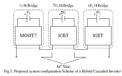
| Energy and environment problem has received greatattention all around the world. As a result, renewable energyis generally welcomed by the public for the characteristics ofpollution-free and reserve-abundant [1-3]. To meet the selfrequirementof high efficiency and high reliability for therenewable energy source, the performance of the powerelectronics interface should be improved [3, 4]. Suitabletopology and control method are needed to reach the highlevel operation.The research work in the paper is focused on the DC-ACpart in the renewable energy system. Based on theconventional structure of cascaded H-bridge inverter, a newkind of hybrid cascaded inverter (HCI) is accomplished.Thehybrid structure is shown in two aspects. Firstly, the DC buses have hybrid voltages. They are V0, 2V0 and 4V0respectively. Secondly, hybrid power devices are adopted.For DC buses with different voltages are employed, morevoltage levels can be reached at the AC side, with ratherlower switching frequency. |
| As a result, the output harmonicloss and the switching loss are lower down. At the sametime, for different kinds of power switches are employed, theperformance of the inverter system can be further improved.According to the selected modulation method, the switchingfrequency in the three H-bridges are different. In V0 Hbridge,the DC bus voltage is lower and the switchingfrequency is higher, so power MOSFET is adopted. On theother hand, in 2V0 and 4V0 Hbridges, the DC bus voltageishigher and the switching frequency is lower, so IGBT isadopted. With the above combination of power switches, theadvantages of different devices can be shown and the systemloss is further lowered down. The high efficiency operationof the inverter system can be reached.Compared with conventional two-level inverter, HCI hasseveral advantages. They’re flexible choice of devices, lowvoltage rating for each power switch, low output harmoniccontent, low switching frequency and so on. At the sametime, it should be emphasized that with the rapid progressionof renewable energy generation system, the concept of‘Micro-grid’ is highly concerned worldwide [5-7]. ‘Microgrid’includes several micro-sources inside and the abovestructure of HCI has several DC input ports. As a result, HCIis suitable for the application of Micro-grid. Its DC side canbe easily connected to the micro-sources with DC voltageoutput.In this paper, a 2kW single-phase HCI is implemented. Itis based on low-loss MOSFET (offered by IXYS Co.) andV-IGBT (offered by Fuji Electric Co.). Voltage gradationaland PWM carrier modulation methods are employed. Therealization process of the two methods is showntheoretically. The structure of HCI and the two modulationmethods are validated by simulation. |
 |
STRUCTURE OF HCI AND ITS MODULATION METHOD |
| The structure of the HCI is composed of three H-bridges,as shown in Fig.1. They have isolated DC buses and thevoltages are V0, 2V0 and 4V0 respectively. And at the ACside, three H-bridges are connected in series. Concretely, V0 H-bridge is based on MOSFET, while 2V0 and 4V0 H-bridgesare based on V-IGBT.In the paper, two kinds of modulation methods areemployed. First is voltage gradational method and second isPWM carrier method. In voltage gradational method, V issupposed to be the required voltage at the AC side. It is thesuperposition result of V0, 2V0 and 4V0, as shown in (1).Here, coefficients x, y and z equal to 1, -1 or 0. ‘1’, ‘-1’ and‘0’ mean the H-bridge outputs positive, negative and zeroDC bus voltage, respectively. It can be analysed that to eachneeded voltage at the AC side, several superposition wayscan be reached sometimes. For example, V0 has threesuperposition methods. They can be shown as‘V=1·V0+0·2V0+0·4V0’, ‘V=(-1)·V0+1·2V0+0·4V0’ and ‘V=(-1)·V0+(-1)·2V0+1·4V0’. In this way, some redundant statescan be reached. The operation of HCI is more flexible (it willbe shown in detail in the following part). |
 |
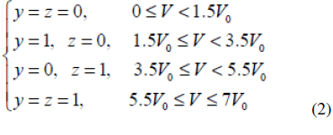
| The realization process of voltage gradational modulationmethod can be shown as follow. Firstly, according to theactual required amplitude and frequency, confirm the idealinstantaneous voltage value. Secondly, divide the idealinstantaneous voltage by the reference voltage V0. Round theresult and get the voltage level to the instantaneous voltage.Finally, confirm the concrete output voltage of each Hbridgeand the concrete state of each power switch.In order to lower down the contents of low frequencyharmonic components, PWM carrier modulation method isemployed. In this method, the outputs of 2V0 and 4V0 Hbridgesare kept same as voltage gradational method. Thesum of the above two output voltage waveform has sevenlevelstaircase. The ideal sinusoidal waveform minus thesevenlevel staircase waveform reaches the modulation wavein V0 H-bridge. So, PWM method is employed and the sumof the output waveforms in three H-bridges approximates tothe ideal sinusoidal wave. Also, suppose V is the object voltage at the AC side, asshown in (1). With PWM carrier modulation method, in thepositive half period, the coefficients y and z are confirmed asshown in (2). From (2), the output of 2V0 and 4V0 H-bridgesare reached. The corresponding output voltage in V0 Hbridgeis got by the comparison of the above modulationwave and triangle carrier wave. |
 |
POWER BALANCE CONTROL METHOD IN HCI |
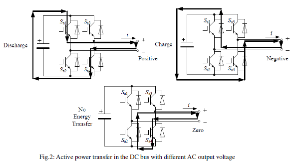
| As mentioned in Part II, in voltage gradationalmodulation method, there are several redundantsuperposition methods. The redundant states can be utilized.As commonly known, one H-bridge can output three kindsof voltages. They’re positive DC bus voltage, negative DCbus voltage and zero. Suppose the direction of the loadcurrent is shown in Fig.2 (When the direction of the loadcurrent changes, the same analyzing process can bereached.). When positive voltage is reached at the AC side,the DC bus provides active power and the capacitor isdischarging. At the same time, when negative voltage isreached, the DC bus absorbs active power and the capacitoris charging. When zero voltage is reached, no active power istransferred in the DC bus capacitor. HCI has several DC input ports. In the actual application,the DC bus can be connected to different kinds of sources.For example, it can be connected to photovoltaic (PV) panel,storage battery, and so forth. As known that, storage batterycan store energy when the input energy is adequate in theinverter system, such as sufficient light for PV system. Onthe other hand, it can release energy when the input energy isinadequate. As a result, with different external conditions,the distribution of active power at the DC side should beadjusted accordingly. Take the following system as anexample. The DC buses of V0 and 2V0 H-bridges areconnected to storage battery and the DC bus of 4V0 Hbridgesis connected to PV panel. When sufficient sunlight isreceived in the system, 4V0 H-bridge should provide moreactive power, while at the same time, V0 and 2V0 Hbridgesshould absorb active power and store energy. |
 |
| When noenough sunlight is received, 4V0 H-bridge should provideless active power and the other two bridges with storagebatteries should provide more. The above power balanceprocess is reached by selecting different superpositionmethods.Also, when starting up HCI, the DC bus capacitor shouldbe precharged. It can be simply accomplished by selectingdifferent superposition methods. Also take the abovesituation as an example. When starting up the HCI, theprecharging process can be reached by selecting thesuperposition method of (x, y, z) = (-1,-1, 1). Here, (x, y, z)represents the concrete superposition method. It means thatV0, 2V0 and 4V0 H-bridges output negative, negative andpositive DC bus voltage. So the active power in 4V0 Hbridgeflows to the V0 and 2V0 H-bridges. Three DC buscapacitors are precharged by the PV panel connected to 4V0DC bus. |
 |
SIMULATION RESULTS |
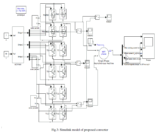
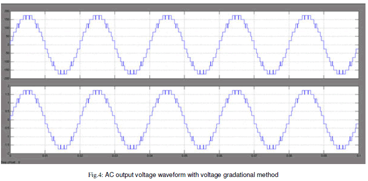
| In order to verify the feasibility of the hybrid cascadedstructure and the two modulation methods, simulation modelbased on MATLAB/SIMULINK is implemented. In themodel, three H-bridges are adopted. The structure is as sameas mentioned above. Furthermore, a 2kW prototype is builtup, as shown in Fig.3. In both simulation, Theload voltage of 220V (rms) is set up and inductive load of15mH 200Ω is adopted. The output frequency is 50Hz. TheAC output waveforms with the two modulation methods areshown in Fig.4 and 5. From Fig.4 and 5, it can be seen that both methods canreach staircase voltage waveform at the AC side. Concretely,the simulation FFT analysis results of ACoutput voltage are shown in Table I (without filtering). |
 |
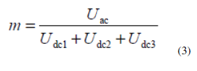
| Thebase frequency is set to 50Hz. It can be seen that with thesame modulation object, PWM carrier method has lowerlow-frequency output harmonic contents than voltagegradational method. harmonic contents are alittle higher than simulation results. It is because moreswitching transient states are involved.Define the voltage utilization ratio of HCI as follow in(3). Here, ‘m’ represents voltage utilization ratio. Udcx (x=1,2, 3) represents DC bus voltage. Uac represents the rms valueof AC voltage. So, in simulation, with voltage gradational method, mequals to 0.71, while with PWM carrier method, m equals to0.65. And in experiment, with voltage gradational method, mequals to 0.76, while with PWM carrier method, m equals to0.68. It can be concluded that simulation results are approximately in accordance and voltagegradational method has higher voltage utilization ratio thanPWM carrier method.In order to reach higher energy conversion efficiency, itis required to evaluate the conversion efficiency. |
 |
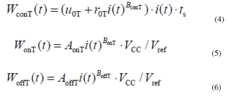
| In HCI,low-loss MOSFET offered by IXYS Co. and V-IGBToffered by Fuji Electric Co. are employed. The simulationefficiency evaluation process can be summarized as follow.Firstly, the analytical expression of each kind of power lossis confirmed, including the undetermined coefficients.Secondly, according to the datasheet, confirm the aboveundetermined coefficients by curve fitting. Finally, calculate each kind of power loss and conversion efficiency.Concretely, to IGBT, the steady state loss, turn-on loss andturn-off loss are expressed by (4) ~ (6). To MOSFET, thesteady state loss and transient state loss (the turn-on and turnoffloss are unified as transient loss) are expressed by (7) and(8). The steady state loss of the free-wheeling diode in bothbridges is expressed in (9) and the reverse recovery loss ofthe free-wheeling diode in IGBT bridge is expressed in (10). |
 |
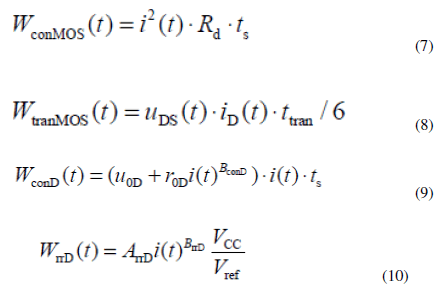 |
| Fast-recovery diode is adopted as the free-wheeling diode inMOSFET bridge and the time-span of the reverse recoveryprocess is further less than that in IGBT bridge. As a result,the reverse recovery loss of the free-wheeling diode inMOSFET bridge is ignored. Here, ‘WconT’, ‘WonT’ and ‘WoffT’are the steady loss, turn-on loss and turn-off loss of IGBTrespectively. ‘WconMOS’ and ‘WtranMOS’ are the steady loss andtransient loss of power MOSFET. ‘WconD’ is the steady lossof free-wheeling diode in both bridges and ‘WrrD’ is thereverse recovery loss of freewheeling diode in IGBT bridge.‘Vcc’ is the actual DC bus voltage and ‘Vref’ is the DC busvoltage shown in the datasheet; ‘i’ is the current flowingthrough the power switch. ‘Rd’ is the on-state resistor ofMOSFET. In (8), ‘uDS’ is the voltage across terminal ‘D’ and‘S’ when MOSFET is turned off and ‘iD’ is drain currentwhen MOSFET is turned on. At the same time, ‘ttran’ is thetime-span of the turn-on or turn-off process. In (4), (7) and(9), ‘ts’ is the control period. The other parameters are theundermined coefficients. Then, according to the datasheet ofV-IGBT and low loss MOSFET, by curve-fitting, theundetermined coefficients can be reached, as shown in TableI. So, the system power loss and efficiency can be achieved. |
 |
| The simulation evaluation result is shown in Fig.6. It canbe seen that both methods realize high conversion efficiency(>98%) and voltage gradational method gets a higherefficiency than PWM carrier method. It is because withvoltage gradational method, the highest switching frequencyis 700Hz (in V0 H-bridge), while with PWM carrier method,the highest switching frequency is 10kHz (also in V0 Hbridge).No high frequency switching process is involved involtage gradational method and switching loss is furtherlowered down.The experiment results of conversion efficiency can beshown as follow. With voltage gradational method, theexperiment efficiency is 96.6% and with PWM carriermethod, the result is 94.4%. The corresponding simulationresults to the above experiment results are 97.6% (withvoltage gradational method) and 96.4% (with PWM carriermethod). It can be seen that the experiment results areslightly smaller than the simulation results. It is because thatline impedance isn’t considered in simulation and themeasurement error caused by the probe cannot be completelyeliminated. It should be noticed that the output power andvoltage level are kept same in both simulation results above, although for safety, the powerlevel is smaller than that in Fig.4. |
| In order to verify the power balance performance,different kinds of AC voltage superposition methods aretested. Take three situations as examples, shown in Table I.To each H-bridge, ‘psv0’, ‘ps2v0’ and ‘ps4v0’ represent theactive power provided by the front micro-source in each Hbridge;‘pinvv0’, ‘pinv2v0’ and ‘pinv4v0’ represent the active powertransferred to the load. The values of above parameters in thethree situations are shown in Fig. 5. It can be concluded thatwith different voltage superposition methods, the powerdistribution at the DC side can be changed. The operation ofHCI is more flexible. |
 |
CONCLUSION |
| In order to improve the performance of the renewableenergy system, HCI is employed. In this paper, the topologyand modulation method of a single-phase HCI are discussed.Concretely, hybrid power devices are involved. In V0 Hbridge,power MOSFET is adopted while in 2V0 and 4V0 Hbridges,IGBT is employed. The advantage of each kind ofdevice can be shown. The HCI is composed of three Hbridges.The DC voltage of each H-bridge meets theproportional relationship of 1:2:4 and their AC sides areconnected in series. |
| As a result, it can output more voltagelevels at the AC side with lower switching frequency. At thesame time, voltage gradational and PWM carrier modulationmethods are adopted and discussed in detail in the paper.Based on the simulation results,it can be concluded that high conversion efficiency (>98%)and good output performance (THD<5%) of HCI arereached. And with different combination of switching states,the distribution of input active power at the DC side can beadjusted. |
References |
|