ISSN ONLINE(2278-8875) PRINT (2320-3765)
ISSN ONLINE(2278-8875) PRINT (2320-3765)
Nitin goel1, Shilpa2, Shashi yadav2
|
| Related article at Pubmed, Scholar Google |
Visit for more related articles at International Journal of Advanced Research in Electrical, Electronics and Instrumentation Engineering
The UPFC is a member of the FACTS family with very attractive features and it is a solid state controller which can be used to control active and reactive power flow in a transmission line. In this paper the performance of Unified Power Flow Controller (UPFC) is investigated in controlling the flow of power over the transmission line. This research deals with simulation of transmission line using UPFC to improve the real and reactive power flow control through a transmission line. In this research paper a Simulink Model is considered with UPFC model to evaluate the performance of a single and double transmission line systems (22/6.6) kV. In the simulation study, the UPFC models ease the real time control and dynamic compensation of AC transmission system. It should be consider as real and reactive power compensation, capable of independently controlling voltage profile as well as the real and reactive powers in the line. The simulation model is tested for single and double transmission line systems with and without UPFC model in MATLAB/SIMULINK environment. By using a UPFC the oscillation introduced by the faults, the rotor angle and speed deviations can be damped out quickly than a system without a UPFC. It is also shown that a UPFC can control independently the real and reactive power flow in a transmission line.c
Keywords |
| FACTS, OPF, Power system, UPFC, N-R method, power flow controller |
INTRODUCTION |
| As the load increases, demand of power utilities is increases due to this the utilization of their existing transmission system increases. Continuous and fast improvement of power electronics technology has made Flexible AC Transmission System (FACTS) a good concept for power system development. Among a variety of FACTS controllers, UPFC have attractive feature so it is discussed in detail. UPFC is an advanced power systems device capable of providing simultaneous control of voltage magnitude and active and reactive power flows. UPFC was proposed for real time and dynamic compensation of AC transmission systems, providing the necessary functional flexibility required to solve many problems which are faced by the utility industry. The UPFC is an advanced power system device capable of providing simultaneous control of voltage magnitude, active and reactive power flows in an adaptive fashion. It has |
| • Extended functionality |
| • Capability to control voltage, line impedance and phase angle in the power system network |
| • Enhanced power transfer capability |
| • Ability to decrease generation cost |
| • Ability to improve security and stability |
| • Applicability for power flow control, loop flow control |
| In this paper, a comprehensive method is developed for power flow analysis of a transmission system with UPFC Simulink Model to evaluate the performance of a single and double transmission line system has been focused. A mathematical model of UPFC has been developed to study the characteristics using state space calculations without considering the effects of converters and the dynamics of generator. The aim of this technique is to control the real and reactive power flow in the transmission lines, by effectively changing the firing angle of shunt converter and modulation index of the series converter the two leg three phase converters based on UPFC. They suggests that the UPFC with their controller successfully increase the real as well as reactive power flow and improves voltage profile for the duration of the transient conditions in the power transmission systems. Some results of network with and without UPFC are also been compared in terms of active and reactive power flows in the line. A number of simulation results have compared when UPFC is connected between two transmission line with a transmission line without UPFC. The performance of UPFC in controlling power flow over the transmission line is investigated. |
MODELLING OF UPFC |
| The UPFC consists of two switching converters, which are considered as voltage sourced inverters using gate turn-off (GTO) thyristor valves (as shown in fig.1). These inverters labelled “Inverter 1” and “Inverter 2” in the figure is operated from a common dc link provided by a dc storage capacitor. The function of this arrangement as an ideal ac to ac power converter in which the real power can freely flow in either directions between the ac terminals of two inverters and each inverter can independently generate (or absorb) reactive power at its own ac output terminals. Inverter 2 provides the main function of UPFC by injecting an ac voltage Vpq , in line via an series transformer with controllable magnitude Vpq (0≤Vpq≤Vpq) and phase angle ρ (0≤ ρ≤2π), at the power frequency. This injected voltage can be considered essentially as a synchronous ac voltage source. The real power exchanged at the ac terminal is converted by the inverter into dc power which appears at the dc link as positive or negative real power demand. The reactive power exchanged at the ac terminal is generated internally by the inverter. The basic function of Inverter 1 is to supply or absorb the real power demanded by Inverter 2 at the common dc link. This dc link power is converted back to ac and coupled to the transmission line via a shunt-connected transformer. Inverter 1 can also generate or absorb controllable reactive power, if it is desired, and thereby it can provide independent shunt reactive compensation for the line. The reactive power exchanged is supplied or absorbed locally by inverter 2 and therefore it does not flow through the line. Thus, inverter 1 can be operated at a unity power factor or be controlled to have a reactive power exchange with the line independently of the reactive power exchanged by Inverter 2. |
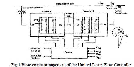 |
| This means that there is no continuous reactive power flow through the UPFC. When viewed the operation of the UPFC, it can perform the functions of reactive shunt compensation, series compensation and phase shifting simultaneously; thereby can meet multiple control objectives by adding the injected voltage Vpq, with appropriate amplitude and phase angle, to the terminal voltageV0. With these assumptions the series voltage source, together with the real power coupling to the sending end generator is an accurate representation of the basic UPFC. |
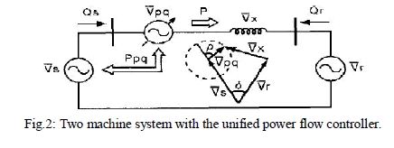 |
| The N-R method is adopted for solving the power flow problem; the N-R iterative step will take the role of the time variable in dynamic systems. In this way, the dynamic responses of the UPFC controllers can be simulated as the network variables change as the N-R iteration counter increases towards its final value at convergence. |
At node s: |
SIMULATON AND RESULTS |
| The concept of the control system, in a transmission line is taken to implement the use of UPFC. The two control modes that is voltage injection mode and the power flow control mode is simulated in simulink model to see the effect of UPFC on a transmission line. It is carried out to verify the utility of UPFC device. The UPFC could be considered as comprehensive reactive power and real power compensation capable of independently controlling the real and reactive powers in the line and voltage profile. The corresponding simulation models with and without UPFC are developed in MA TLAB / SIMULINK environment for the following cases. |
INVESTIGATION OF TRANSMISSION LINE WITHOUT UPFC: |
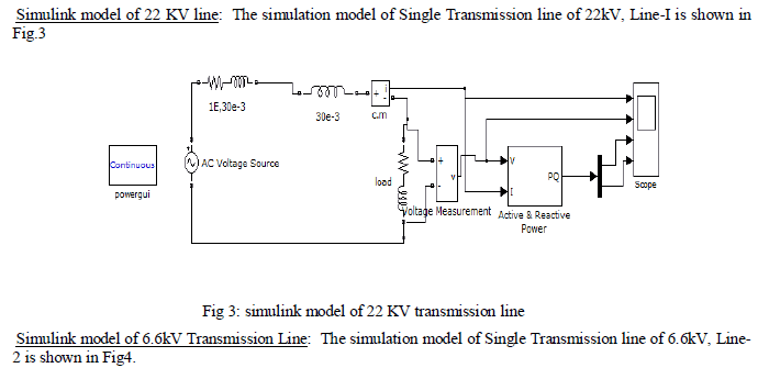
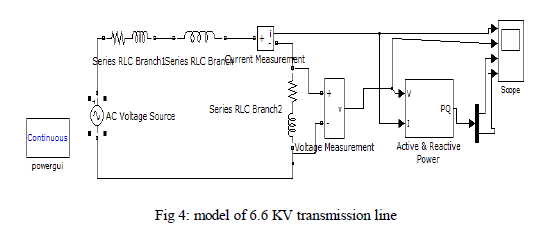
| The function of the electric power system is to supply electrical energy to consumers which is economical as well as reliable. An efficient transmission system has capability to provide the transfer of electrical energy between the point of supply and the delivery. Transmission line performance assessment depends on data collection capabilities and performance metrics to ensure continued grid adequacy and security. The testing of transmission line without UPFC device in MA TLAB /SIMULINK model has been discussed in the following sections. |
 |
 |
B. INVESTIGATION OF TRANSMISSION LINE WITH UPFC: |
| With the development of power systems it is more important to control the power flow along the transmission line, thus to meet the need of power transfer. On the other hand with the fast development of power electronic technology has made UPFC a hopeful part for future power system needs. This device is an advanced power system device capable of providing simultaneous control of voltage magnitude, active and reactive power flows in an adaptive fashion. The testing of transmission line with UPFC device in MA TLAB / SIMULINK models is discussed in the following section. |
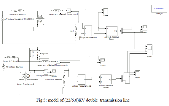
| Simulink Model of 6.6 kV/22kV Transmission Lines: The Simulink Model is shown in Fig.5 represents the double line transmission model which consists of normal circuit and compensation circuit with an UPFC device. The compensation circuit, Line-I i.e. 22kV can absorb real power to the DC link through the converter or rectifier present in the UPFC system. From the DC link, in normal period, the normal circuit, Line-2 that is 6.6kV can give real power from DC link through converter or inverter. The real power needed by the compensation circuit to mitigate the compensation is exactly equal to the real power delivered by the normal circuit which includes both line and converter switching losses. |
 |
| The sub-system of the UPFC model that is interconnected to the double transmission line models with different rating as shown in Fig .6 |
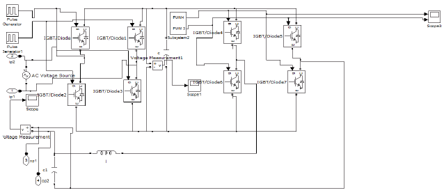 |
| Fig 6: UPFC sub system model |
C. SIMULATION RESULTS AND DISCUSSION |
| Result of 22 kv line without UPFC: The model is simulated and corresponding results of voltage magnitude, real and reactive power flows are shown in Figs.7respectively. |
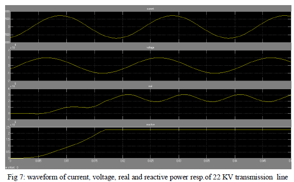 |
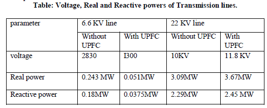
| By observing the above wave forms, the voltage magnitude is 9.754kV, the real power is 3.05e6 and the reactive power is 2.28e6 |
| Result of 6.6 kv line without UPFC: The model is simulate and corresponding results of voltage magnitude, real and reactive power flows are shown in Fig 8. |
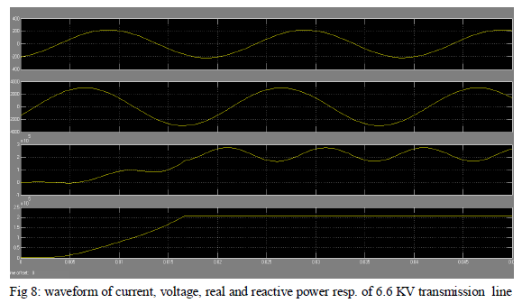 |
| By observing the above wave forms, at steady state time t = 0.02sec the voltage magnitude is 2.926kV, the real power is 1.746e5 and the reactive power is 1.953e5. |
| Result of (22/6.6) kv double line with UPFC: The corresponding voltage waveform of 22kV line with compensation and the real and reactive power waveforms are shown in Fig9. |
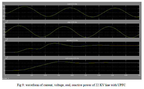 |
| By observing the above wave forms, at steady state time, t =0.02sec, the voltage magnitude is 11kV, the real power is 3.4e6 and the reactive power is 2.4e6for 22kV line. The voltage wave form, the real and reactive power waveforms of 6.6kv line with compensation are shown in Figs.10 respectively. |
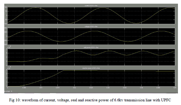 |
| By observing the above waveforms, at steady state time, t:=0.02sec, the voltage magnitude is 1.3 k V, the real power 0.5e5 and the reactive power is 0.37e5. |
 |
CONCLUSIONS |
| In the simulation study, MA TLAB SIMULINK model is used to simulate the model of UPFC connected with transmission lines i.e. 22kv/6.6kv. This work gives performance of the UPFC used for power quality improvement and to obtain the steady state objectives achievable by control settings of the UPFC controllers .The UPFC concept provides a powerful tool for the cost effective utilization of individual transmission lines by facilitating the independent control of both the real and reactive power flow. There is an improvement in both voltage and power profiles, through the transmission line when UPFC is incorporated in the system. |
| The proposed model can also be applicable to modulate the active power by reactive voltage injection. Through this, it may be possible to bring vast improvement of power flow in transmission system. |
References |
|