International Journal of Advanced Research in Electrical, Electronics and Instrumentation Engineering
ISSN ONLINE(2278-8875) PRINT (2320-3765)
ISSN ONLINE(2278-8875) PRINT (2320-3765)
| S. Yang Assistant professor, Dept. of EE and CS, CETPS, Alabama A & M University, Huntsville, Alabama, USA |
| Related article at Pubmed, Scholar Google |
Visit for more related articles at International Journal of Advanced Research in Electrical, Electronics and Instrumentation Engineering
A microwave square ring resonator is a narrow band bandpass filter (BPF) that can be widely used in microwave filters and oscillators. But its spurious harmonics generate harmful electromagnetic interferences, and must be removed. In this paper, two spurlines are tuned to suppress the first and the second harmonics of a square ring resonator. Simulations show both harmonics can be highly suppressed.
Keywords |
| Spurline, Bandstop, Harmonic, Suppression |
INTRODUCTION |
| Microwave BPF is being widely used in telecommunication systems. Various techniques have been developed to design and synthesis BPFs [1]. One big issue of microwave BPFs is their spurious harmonics [2-4], which can deteriorate their stopband performance and generate electromagnetic interference. The microstrip ring resonator is a very narrow band BPF [5], and it is widely used in microwave systems. In this paper, two spurlines are added into the feeding lines of a square ring resonator to suppress its first and the second harmonics. Simulations show lengths of the two spurlines need to be tuned carefully from calculated values and the two harmonics can be highly suppressed. |
RELATED WORK |
| A microwave square ring resonator has narrow passbands. Oscillations can happen if the perimeter of the ring equals to the wavelength or the wavelength multiplied by an integer [5]. Spurline was proposed by Bates to generate bandstop filters (BSFs) [6]. The stopband happens when the length of the spurline equals to a quarter of the wavelength. A spurline is realized by etching an L-shaped slot on a microstrip. A spurline BSF can generate moderate rejection bandwidth. The first two harmonics of a square ring resonator have relatively narrow bandwidths. The two spurelines in the feeding lines of the square ring resonator can generate two stopbands wide enough to suppress the two harmonics of the resonator. |
THE SQUARE RING RESONATOR |
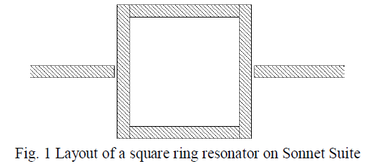
| A square ring resonator is shown in Fig. 1. The substrate material is Rogers TMM10i with a relative dielectric constant of 9.8 and a loss tangent of 0.002. The thickness of the substrate is 1.27 mm. The whole backside of the substrate is the ground plane. The width of the feed lines and the width of the ring line are 1.2 mm, which gives a characteristic impedance of 50 Ohm. The average perimeter of the ring is 47.59 mm. The gap between the ring and two feeding lines is 0.30 mm. |
 |
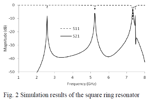
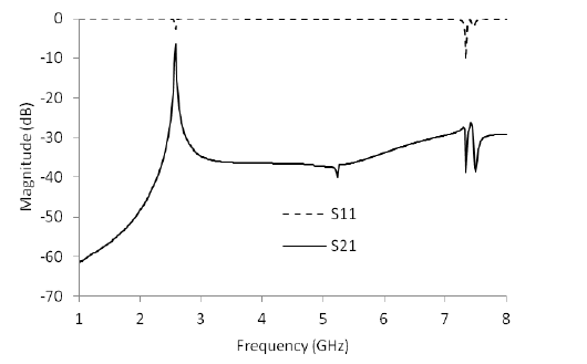
| This square ring resonator is simulated on Sonnet Suite 14.52, and the results are shown in Fig. 2. The fundamental frequency is at 2.58 GHz, and the first and the second harmonics are around 5.24 GHz and 7.34 GHz respectively. These two harmonics need to be removed to get rid of harmful interference from them. |
 |
SPURLINE |
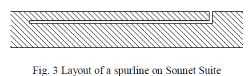
| A typical spurline is shown in Fig. 3. It is formed by etching an L-shaped slot on a microstrip. The microstrip is 1.20 mm wide. The width of the spurline is at 0.30 mm, and the length of the spurline is 6.0 mm, and the gap (or the slot width) is at 0.10 mm. |
 |
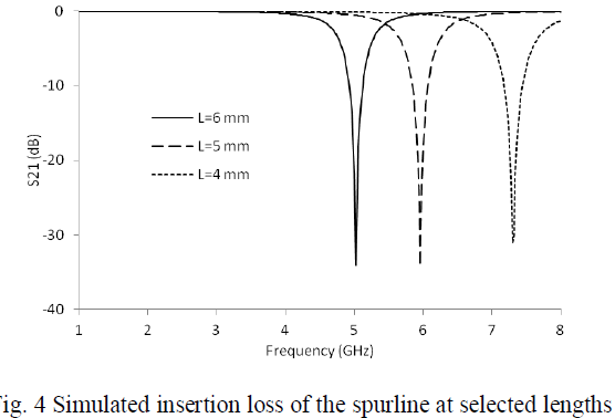
| First, the spurline is simulated on Sonnet Suite at selected lengths with fixed width 0.3 mm and fixed gap 0.1 mm. The simulation results are shown in Fig. 4. The stopband center frequency decreases with spurline length as expected. |
 |
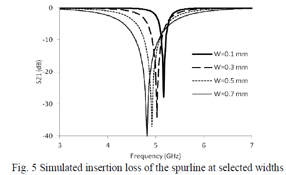
| Secondly, the spurline is simulated with selected widths at fixed length 6 mm and fixed gap 0.1 mm. Simulation results show the stopband gets deeper and wider with larger spurline width (Fig. 5). The stopband frequency shifts down a little bit with larger spurline width. This should be caused by open end effect [7]. |
 |
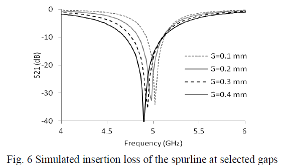
| Thirdly, the spurline is simulated at different gaps with fixed length 6 mm and fixed width 0.3 mm. The stopband gets wider with larger gap at fixed length and fixed width (Fig. 6). The stopband center frequency also shifts down a little bit with larger gap. This effect should be caused by the stronger open end effect from a larger gap. |
 |
HARMONIC SUPPRESSIONS |
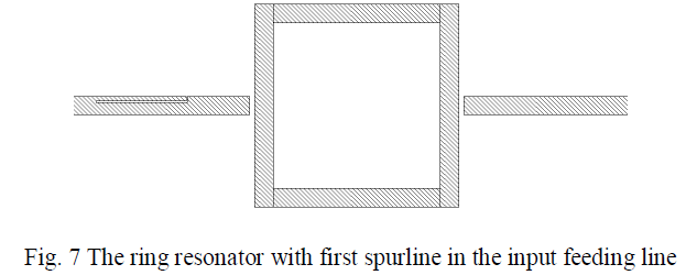
| First spurline is added to the input feeding line of the square ring resonator to suppress the first harmonics at 5.24 GHz. The layout of the setup is shown in Fig. 7. The width of the spurline is chosen as 0.3 mm. The length of first spurline was calculated on AppCAD software as the quarter wavelength at 5.24 GHz on a 0.3 mm wide microstrip line, and the result is 5.78 mm. |
 |
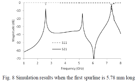
| The whole filter is simulated again and simulation results show that insertion loss S21 has a sharp peak at 5.24 GHz and a deep dip at 6.08 GHz (Fig. 8). The spurline length needs to be tuned to remove the sharp peak, and the deep dip has to be moved to lower frequencies. |
 |
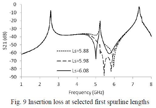
| Next, this spurline length is increased by 0.1 mm, 0.2 mm and 0.3 mm respectively. The simulation results are shown in Fig. 9. When this spurline length is set at 5.98 mm, the first harmonics is very highly suppressed. When this spurline length is at 5.88 mm or 6.08 mm, the first harmonics is not fully suppressed. |
 |
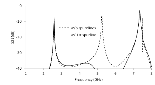
| The insertion loss with and without first harmonic suppression are shown together in Fig. 10 for comparison. The first harmonics at 5.24 GHz is very highly suppressed without much disturbance to the passband around 2.58 GHz. The second harmonics is still there around 7.34 GHz. |
 |
| Fig. 10 Insertion loss S21 without (dashed) and with (solid) first harmonic suppression |
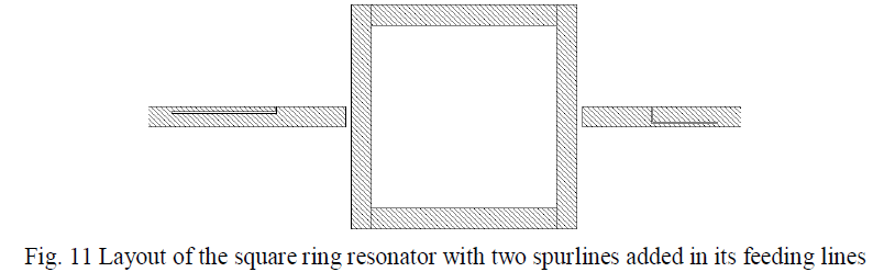
| Second spurline is added to the output feeding line of the square ring resonator to suppress the second harmonics at 7.34 GHz. The layout is shown in Fig. 11. The second harmonics is wider than the first harmonics. So the second spurline width is chosen at 0.90 mm, three times the width of the first spurline. Its gap is kept at 0.1 mm, and the length is calculated as 3.90 mm on AppCAD software directly. |
 |
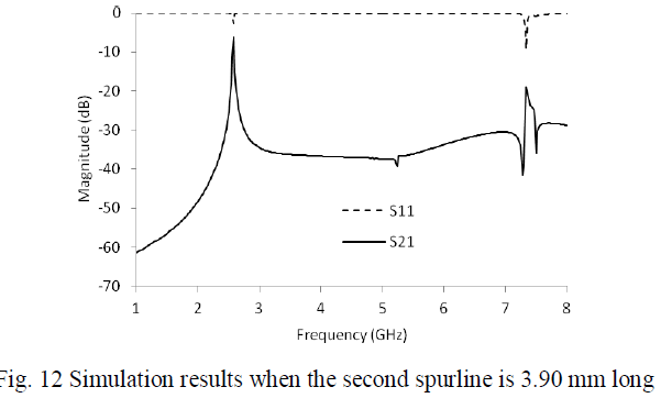
| Then the whole filter is simulated again on Sonnet Suite. The simulation results are shown in Fig. 12. The insertion loss S21 has a deep dip and a high peak around 7.28 GHz. The second spurline needs to be tuned shorter to move this deep dip to higher frequencies. |
 |
| Then the spurline length was carefully tuned to 3.70 mm, and the whole filter is simulated again. Simulation results are shown in Fig. 13. This time the second harmonics is fully removed. |
 |
| Fig. 13 Simulation results when the second spurline is at the right length of 3.70 mm |
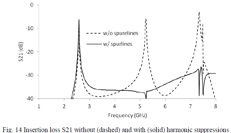
| For comparison, the insertion losses without and with two spurlines are shown together in Fig. 14. The first harmonics is suppressed for more than 30 dB, and the second harmonics is suppressed for about 20 dB. The passband around 2.58 GHz get a little bit wider. |
 |
CONCLUSIONS |
| Two spurlines in the feeding lines of a square ring resonator are used to suppress the first and the second harmonics of a square ring resonator. The square ring resonator has a narrow first harmonic passband and a relatively wide second harmonic passband. The first spureline is 0.30 mm wide, and the second spurline is 0.90 mm wide. The length of the two spurlines need to be slightly tuned from the quarter wavelength at the first and the second harmonic frequencies for microstrips with the same widths as the two spurlines. The first harmonics is suppressed for more than 30 dB, and the second harmonics is suppressed for about 20 dB. The fundamental passband does not get much disturbance after harmonic suppressions. |
ACKNOWLEDGMENT |
| The author would like to thank Dr. Montgomery for his financial help, Dr. Scott for his help to install Sonnet Suite software, and Dr. Heidary for his microwave network analyzer. |
References |
|