ISSN ONLINE(2278-8875) PRINT (2320-3765)
ISSN ONLINE(2278-8875) PRINT (2320-3765)
| Bhaskar Lodh PG Student [Electrical Engineering], Dept. of EE, Bengal Institute of Technology & Management, Santiniketan, Birbhum, West Bengal, India |
| Related article at Pubmed, Scholar Google |
Visit for more related articles at International Journal of Advanced Research in Electrical, Electronics and Instrumentation Engineering
This paper presents the implementation of PID controller in speed control of DC Motor. Due to its simplicity, robustness and successful practical application, PID (Proportional-Integral-Derivative) controllers have become most widely used controller in the industry. There are several different methods through which the PID controller can generate automatic control efficiently. In this paper, the tuning method used for the proposed speed control model of DC motor is Ziegler-Nichols (ZN) tuning algorithm. Here, a computer based model (using SIMULINK) is furnished for obtaining the apt output during the speed control of a dc motor. Now-a-days, dc motors have become the workhorse of the industrial sector due to their easy means of construction and maintenance. Therefore, the performance of the machine needs to be specified using computer aided programs and the control strategy best suited here is PID.
Keywords |
| DC Motor Speed Control, PID tuning, Ziegler-Nichols Method, Matlab-Simulink |
INTRODUCTION |
| The Zeigler Nichols Open-Loop Tuning Method is a means of relating the process parameters - delay time, process gain and time constant - to the controller parameters - controller gain and reset time. It has been developed for use on delay-followed-by-first-order-lag processes but can also be adapted to real processes. |
| In the past decades, control theory has found several developments. Different intelligent control algorithms have been developed so far. However, the PID-type controller is still the most widely used control strategy in industries. Studies even indicate that approximately 90% of all industrial controllers are of the PID-type. In mid 1930s three mode controllers with proportional, integral, and derivative (PID) actions were commercially available and gained widespread industrial acceptance. The PID controller tuning methods can be classified into two main categories (1) Closed loop methods (2) Open loop methods. In 1942, Ziegler and Nichols presented two standard methods to tune a PID-controller. These methods, due to their simplicity and practicality, are still widely used in different industrial and other tuning process. |
DESIGN EQUATIONS |
| For obtaining the speed control model of the dc motor, the parameters needed are – motor speed, voltage, current, resistance and mechanical time constant. The dynamic parameters of the motor are explained by the following equations- |
| Back e.m.f. of the motor, |
 |
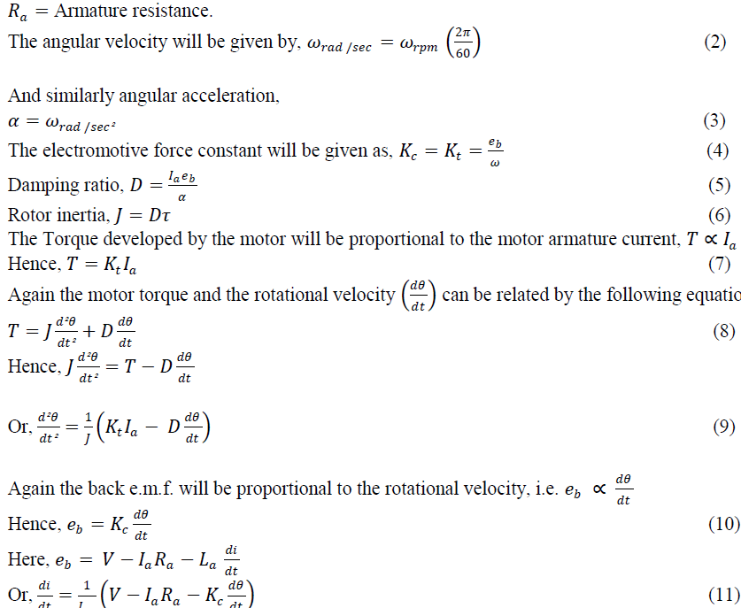 |
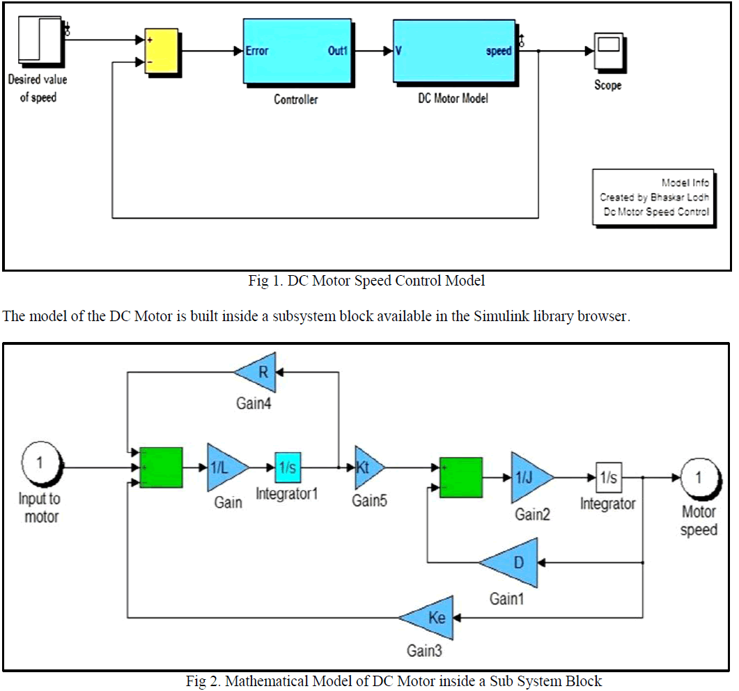
| Using the equations, (9) and (11) the mathematical model of the dc motor is obtained using SIMULINK toolbox. |
INTRODUCTION TO MATLAB – SIMULINK ENVIRONMENT |
| In this paper, the software used for constructing the simulation model is MATLAB. It is a very powerful tool for design engineers. It was first introduced in 1970 by a numerical analyst Cleve Moler, who wrote the first version of MATLAB. Since then, it has become successful computational and profit-making software. SIMULINK is a commercial tool furnished by MathWorks Inc. that comes with MATLAB. It is used for modelling and analysing different types of static and dynamic systems. In this paper, the required simulation model is obtained with the help of different building blocks available in SIMULINK environment. Simulink allows engineers for building any dynamic system using block diagram notation. Using Simulink, it is easy to model any type of complex or non-linear systems. There are several MATLAB functions and toolboxes available in MATLAB environment for processing and plotting of waveforms from analyse data. Simulink provides a stage for professionals to plan, analyse, design, simulate, test and implement different type s of systems. Simulink-Matlab combination is very functional for developing algorithms, creation of block diagrams and analysis of different simulation based designs. |
TEST SYSTEM |
| Here a SIMULINK Model of DC Motor is shown below (refer to Fig. 1). The Mathematical model of the DC Motor and the controller is kept inside a mask (Sub System, refer to Fig.2). |
 |
| For testing the proposed model following system parameters were used for simulation- |
| Terminal Resistance (Ra) = 0.5 Ohm, Terminal Inductance (La) = 1.52 mH. |
| Torque Constant (Ke) = 0.05 Nm/ A. |
| Motor /Load Inertia (J) = 0.00025 Nm/rad/ S². |
| Damping ratio (D) = 0.0001 Nm/ rad/ Sec. |
| Motor Speed Constant (Ke) = 0.05 V/rad/Sec. |
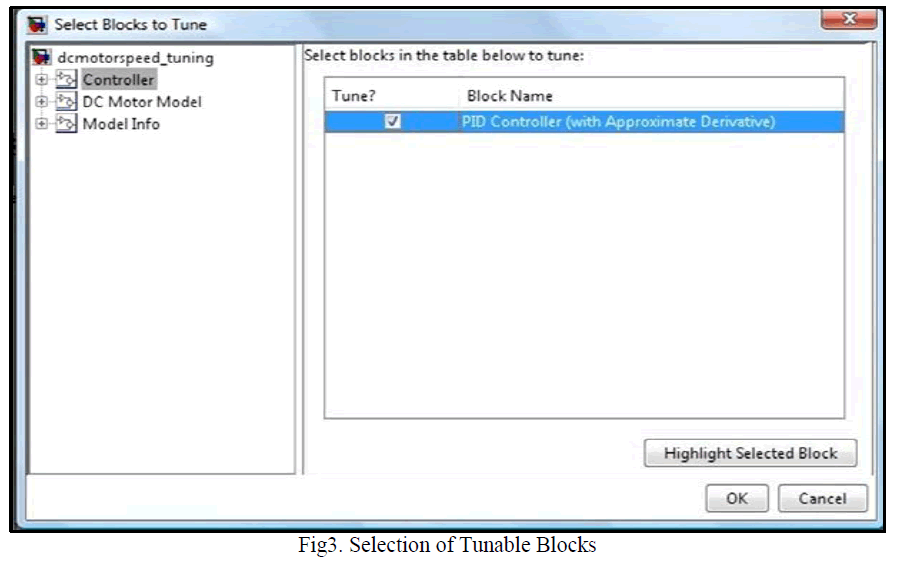
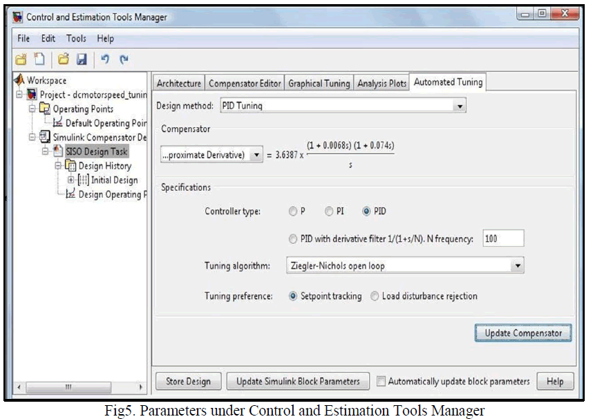
| Here, for designing the compensator, automated PID Ziegler- Nichols open loop tuning algorithm is used. This tuning method computes the proportional, integral and derivative gain of the system. For simulation, Simulink Compensator Design Task is used, which is available in Control Design menu under Tools head. Here, the Controller Sub system is selected as tunable block. The block is tuned by PID controller with approximate derivative check box selected (refer to |
 |
| The initial response of the designed system is shown in the following figure. |
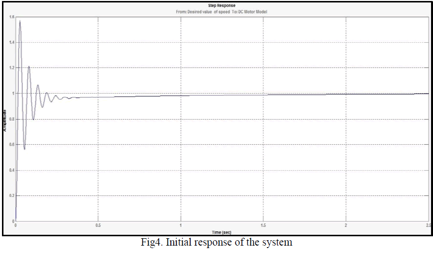 |
| In first response of the model, the settling time came out to be 0.885 second with a Maximum overshoot of 57.1 %. Next, for obtaining an optimum output with reduced value of peak overshoot, the Automated Tuning method is applied, which is available in the SISO Design Task node under the Control and Estimation Tools Manager (refer to Fig.5). Here, the type of controller selected is PID, with Ziegler’s- Nichols open loop as tuning algorithm selected. |
 |
| With, Ziegler’s- Nichols tuning algorithm, the response of the system will be as shown in the following figure |
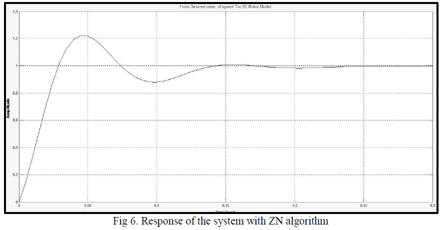 |
| In the second simulation, with Ziegler’s- Nichols tuning method, the response is shown in the above figure. Here, the value of settling time came out to be 0.133 second with a maximum overshoot of 22.1 %. |
CONCLUSION |
| Initial peak overshoot of the system was very high. But with the use of automated PID Ziegler-Nichols open-loop tuning algorithm, the overshoot of the system gets reduced drastically. The settling time of the second simulation was also very less as compared to the first one that is the conventional method, that didn’t meet the design requirement. |
References |
|