ISSN ONLINE(2278-8875) PRINT (2320-3765)
ISSN ONLINE(2278-8875) PRINT (2320-3765)
Abhishek1, Abhinandan Tripathi2
|
| Related article at Pubmed, Scholar Google |
Visit for more related articles at International Journal of Advanced Research in Electrical, Electronics and Instrumentation Engineering
The dynamical model of an original six-rotor is presented in this paper. The helicopter is composed of six rotors with constant pitch propellers; the six rotors are arranged as three counter-rotating offset pairs mounted at vertices of a triangular frame, with matched sets of counter-rotating rotor blades. Differential thrust from these three equally spaced points make helicopter able to manoeuvre quickly and precisely. Euler–Lagrange approach is used to obtain the dynamical model. Classical Linear Feedback control and nonlinear control strategy are proposed for control. The roll and the forward displacement are controlled by using a nested saturation control law. The pitch and lateral displacement are controlled in a similar way.
Keywords |
| Helicopter, Mini-rotorcraft, Non-linear control, 3 Point six rotors (3P-MAV6). |
INTRODUCTION |
| Autonomous mini-aerial vehicles are proving their utility in numerous civil and military applications. The improvement of the capabilities of the existing flying vehicles requires contributions from different disciplines including aeronautics, electronics, signal processing, computer science etc. Similar to classical helicopter, a UAV should be able to perform hover as well as forward flight. A three-point six-rotor MAV (3P-MAV6) is an interesting alternative to the classical helicopter. A 3P-MAV6 is mechanically simpler than a helicopter since it has propellers with constant pitch and does not require a swash plate. The 3P-MAV6 maintenance is therefore simpler than that of a classical helicopter. |
| In view of the interest for the development of micro-UAV, several different aero dynamical configurations have been studied [1-4]. The paper focuses on a multi-rotor rotorcraft having six rotors with constant pitch propellers and no swash plate. The innovative design has three counter-rotating offset pairs mounted at the vertices of an equilateral triangle. It is clear that one of the advantages of 3P-MAV6 with respect to quad rotors and classical helicopter is that the offset layout doubles the thrust without increasing the size of the footprint, and naturally eliminates loss of efficiency due to torque compensation. Coaxial mounting of rotors ensures single point torque balancing. Moreover, if a motor malfunctions, the presence of its coaxial counter-pair mitigates risk and ensures safe landing. |
| The work presented in this paper focuses on the six-rotor MAV which was fabricated in manufacturing laboratory. The three upper rotors rotate in clockwise direction and the lower three in opposite direction. The angular velocity of the rotors can be adjusted to achieve desired roll, pitch and yaw. |
CHARACTERISTICS OF THE 3P-MAV6 |
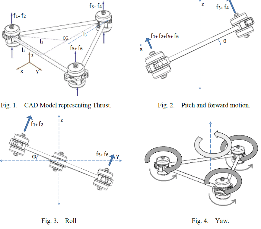
| The following illustrations depict the control approach in broad sense. Fig. (1). The force fi produced by motor i is proportional to the square of the angular speed, that is fi= kωi 2, where k is coefficient of thrust of the propeller. Since each motor turns in a fixed direction, the produced force fi is always positive. The main thrust is sum of individual thrust of each motor i.e. |
 |
| The pitch and roll torque are functions of the difference in thrust and the Yaw torque is the sum τM1+ τM2+ τM3+ τM4+ τM5+ τM6, where τMi is the reaction torque of motor i due to shaft acceleration and the blade’s drag. Using Newton’s second law and neglecting shaft friction, we have IMi 2 1 = −bωi 2+ τMi, where IM is the angular momentum of the ith motor and b >0 is a constant. In steady state, that is, when ÃÅÃâ¡ , the yaw torque is |
 |
| The following motions can be accomplished keeping the total thrust, u constant. |
A. Roll motion: |
| Roll motion is attained using lateral motors. It can be done by increasing speed of (M1, M2) and decreasing speed of (M5, M6) simultaneously. Fig.(3) |
B. Pitch motion: |
| Pitch motion is attained using differential thrust by front and rear motors. It is achieved by increasing speed of (M3, M4) and decreasing speed of (M1, M2) and (M5, M6) simultaneously. Fig. (2) |
C. Yaw Motion: |
| Yaw motion is obtained by increasing the torque of the top motors, τM1, τM3 and τM5, respectively, while decreasing the torque of the bottom motors, τM2, τM4 and τM6. Fig. (4) |
D. Forward Motion: |
| Forward motion is attained by pitching. This motion is obtained by increasing the speed of the rear motors (M3, M4) equally while reducing the speed of the front motors (M1, M2) and (M5, M6). Similarly, the backward motion can also be achieved. Fig. (2) |
 |
DYNAMICAL MODEL |
| This section presents the dynamical model of the 3P-MAV6 using the Euler-Lagrange approach. The following is a derivation of the equations of motion for the rotor-craft assuming it is a rigid body evolving in a 3-D space acted on by gravity, thrust forces and reaction torques generated by the propellers. The dynamics of the six electric motors are fast and, thus, are neglected. Wind disturbances and change in propeller effective pitch with changes in free stream velocity as observed by the propeller (due to vehicle translation and rotation) are also neglected. The generalized coordinates describing rotorcraft position and orientation are |
 |
| where ξ = ( x, y, z)∈R3 denotes the position of the center of mass of the rotorcraft relative to the fixed inertial frame I and η =(ψ, θ, ÃÂÃâ¢) ∈ R3are the three Euler angles. Ψ is the yaw angle around the z-axis; θ is the pitch angle around the modified y-axis and ÃÂÃ⢠is the roll angle around modified z-axis which represents the orientation of the rotorcraft. Model is now separated into rotational and translational coordinates, respectively. |
 |
| The translational kinetic energy of the rotorcraft is given by, |
 |
| where, m denotes the mass of the rotorcraft. The rotational kinetic energy is KErot = (1/2)ωTIω where ω is the angular velocity, I is the inertia matrix. The angular velocity vector ω resolved in the body fixed frame is related to the generalized velocities ïÃÂè (in the region where the Euler angles are valid) by means of the kinematic relationship |
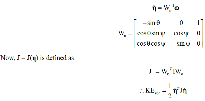 |
| Here J = J(η) is the inertia matrix for complete rotational kinetic energy of rotorcraft expressed in terms of generalized coordinates η. Gravitational potential energy is given by |
 |
| The model of the full rotorcraft dynamics is obtained from Euler-Lagrange equations with external generalized force F as follows: |
 |
| where Fξ∈R3 is the translational force applied to the rotorcraft due to main thrust i.e. control input, R3 represents generalized moments i.e. yaw, pitch and roll moments. The forces acting on rotorcraft expressed on the body frame can be written as |
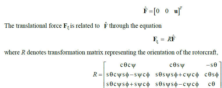 |
| For simplicity, cθ and sθ denote cosθ and sinθ, respectively. The generalized moments on the η variables are denoted by |
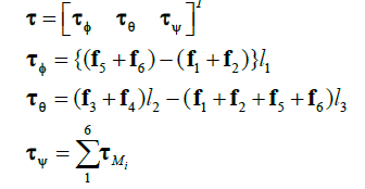 |
| where l1, l2 and l3 are the distances indicated in Fig. 1 |
| Since the Lagrangian contains no cross terms in the kinetic energy, combining ÃÅÃâ¡and ÃÅÃâ¡ , the Euler–Lagrange equation can be partitioned into the dynamics for the translational ξ coordinates and the rotational η dynamics. So, it follows |
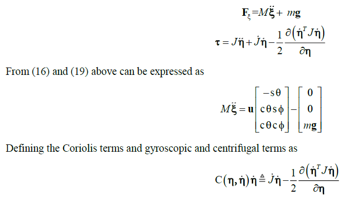 |
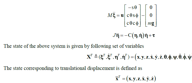
| C is the Coriolis term, which contains gyroscopic and centrifugal terms, associated with the dependence of J. Finally, the dynamical model of rotorcraft is expressed as |
 |
CONTROL STRATEGIES |
| This section presents the control strategy for stabilizing the 3P-MAV6 when operating at hover. The controller synthesis monitors and regulates each state in a sequential manner using a priority rule as follows. We first stabilize the altitude of the rotorcraft using main thrust ‘u’. Next we stabilize the yaw angle and then we control the roll angle ÃÂÃ⢠and the y displacement and finally the pitch angle θ and x displacement are regulated. |
 |
| The proposed control strategy is simple to implement and tune. The experimental setup is such that the four control inputs can independently operate in manual as well as automatic modes. For safety of flight, this feature is particularly important when implementing control strategy. The rotor craft can be operated in semi-automatic mode in which pilot control the coordinates, leaving the orientation stabilization task to control law. |
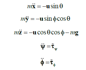
| Roughly, each control input can be used to regulate one or two degrees of freedom as follows: The control input u is primarily used to attain desired altitude. The control input is used to set the yaw displacement to zero. is used to control the roll angle and horizontal displacement along y direction and similarly is used to control pitch and horizontal movement along x-axis. From equation (25), we have |
 |
 |
A. Altitude control |
| The vertical displacement along z is controlled by forcing the altitude to satisfy the dynamics of a linear system. Thus the following control input can be used |
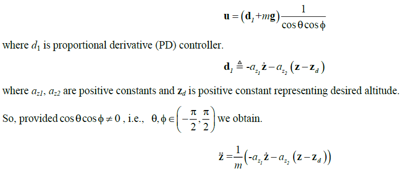 |
| The controller ensures d zz and 0 1 d . The control parameters az1 and az2 should be carefully chosen to ensure a stable and well damped response of the rotorcraft. |
B. Yaw angle control |
| An approach similar to altitude control is used to control yaw angle ψ also. Here also a proportional derivative (PD) controller is used. To control yaw angle, we set |
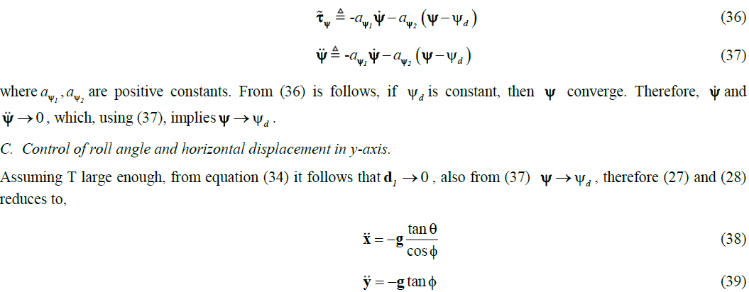 |
| The tri-copter control inputs are subject to physical constraints as in practical, maximum voltage of motors is restricted by input voltage. |
So, we use the control strategy developed in [6]. The nested saturation technique developed in [6] can exponentially stabilize a chain of integrators with bounded input. The amplitudes of the saturation functions can be chosen in such a 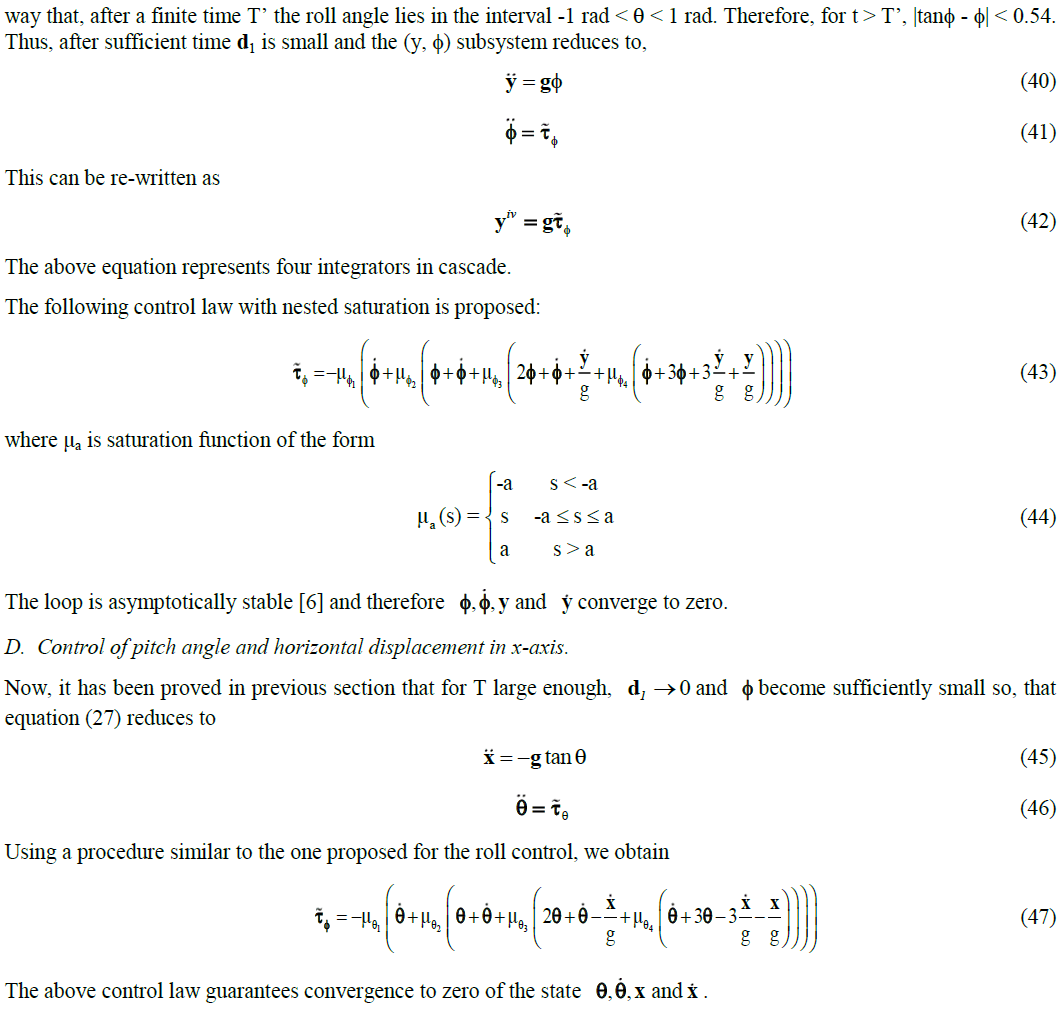 |
SIMULATION RESULTS |
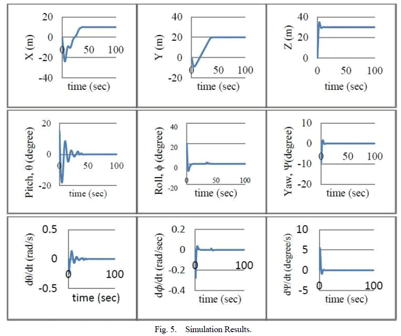
| The proposed non-linear control strategy has been simulated in MATLAB. The rotor-craft was initially at (0, 0, 0, 0, 0, 0). The final co-ordinates assigned were (15, 20, 30, 0, 0, 0). The results show that the physical angles converge to zero and the rotorcraft reaches the destination in finite time as shown in Fig. (5). |
 |
CONCLUSION |
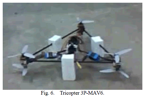
| A novel Tri-copter, Fig. (6) which presents several advantages over the classical helicopters and quad rotors has been presented in this paper. The paper has presented a non- linear dynamical model of the tricopter using Euler-Lagrange approach. A non-linear controller has been proposed which is based on nested saturation technique. |
 |
References |
|