ISSN ONLINE(2278-8875) PRINT (2320-3765)
ISSN ONLINE(2278-8875) PRINT (2320-3765)
P.Sobha Rani1 , Dr. A. Lakshmi Devi 2
|
| Related article at Pubmed, Scholar Google |
Visit for more related articles at International Journal of Advanced Research in Electrical, Electronics and Instrumentation Engineering
Distributed generators are beneficial in reducing the losses effectively compared to other methods of loss reduction. The challenge of identifying the optimal locations and sizes of distributed generation has great research interests nowadays. Many efforts have been made in this direction. In order to minimize line losses of distribution system it is important to define the size and location of DG to be placed. Wih optimal size of DG unit at a suitable location it resulted in reduction in power losses and improvement in voltage . This paper proposes a genetic algorithm based approach for optimal placement of multi distributed generation in a distribution system. The proposed algorithm is tested on IEEE 38 distribution system for locating and sizing of optimal DG source. The DG unit size is calculated by using exact loss formula. With the optimal size of DG unit at a suitable location, it resulted in reduction in real power loss,reactive power loss and improvement in voltage profile.
Keywords |
| Distributed generation(DG), Exact loss formula, Genetic algorithm, Power loss. |
INTRODUCTION |
| With rising prices of oil, the efforts toward the development of alternative energy sources increased. Distributed generators are small generators typically ranging in size from 100 KW to 10MW and can be connected ecnomically to either side of meter. If properly planned and operated, these generators may provide benefits to distribution system by reducing capacity requirements, improving reliability and reducing losses. Examples of DG are diesel generators, small hydro, wind electric systems, solar electric systems,batteries, photo voltaic and fuel cells. DG can be classified into four major types based on their terminal characteristics in terms of real and reactive power delivering capability as follows: |
| 1. DG capable of injecting active power only. |
| 2. DG capable of injecting reactive power only. |
| 3. DG capable of injecting both active and reactive power. |
| 4. DG capable of injecting active power but consuming reactive power. |
| Photo voltaic , micro turbines, fuel cells which are integrated to main grid with the help of converters/ inverters are good examples of type1. Type 2 could be synchronous compensators such as gas turbines. DG units that are based on synchronous machine fall in type 3. Type 4 is mainly induction generators that are used in wind farms. |
METHODOLOGY |
| In a large distribution system network with high powerloss, it is difficult to select a particular bus from many buses so as to place a DG unit for loss reduction. Power losses are present at every bus and identification of bus with highest power loss is important because losses at that bus includes majority of total losses in the system. The cost of power transmission is reduced by minimizing power losses. This can be partially accomplished by DG unit placement in the network. If DG size exceeds certain value of limit, power loss at that bus becomes negative. This situation must be avoided. The beneficial effects of DG mainly depends on its location and size. Selection of optimal location and size of DG is a necessary process to maintain reliability of existing system effectively before it is connected to grid. In this paper exact loss formula is used to determine the size of DG unit. |
PROBLEM FORMULATION |
| The objective is finding the location of DGs and its size to minimize the real power losses and to improve the voltage profile loss in the system can be calculated by equation (1), given the system operating condition, |
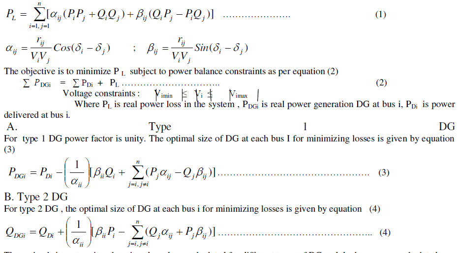 |
| The optimal sizes at various locations have been calculated for different types of DG and the losses were calculated with optimal sizes for each case. The case with minimum losses is selected as optimal location for each type DG. |
PROPOSED ALGORITHM |
| The proposed algorithm is given in following steps: |
| 1.Input line, bus data and bus voltage limits. |
| 2. Calculate loss using distribution load flow based on backward- forward sweep method. |
| 3. Enter number of DGs, type of DG model. |
| 4. Read GA parameters |
| 5. Chromosome length= Chromosome length*No. of DGs. |
| 6. Set generation count=1. |
| 7. Set population count=1. |
| 8. Set Pgen (i) =0, I type(i) =1. |
| 9. Decode chromosome and get location, size of all DGs. |
| 10. If bus voltage is within limits, Calculate total loss as per equation (1). |
| 11. If fit (i) =fit(psize), elitism, selection, crossover, mutation. |
| 12. If iteration number reaches maximum limit, go to step 13, otherwise go to step 6. |
| 13. Print out optimal location and size of DG or multi DGs and corresponding fitness value represents minimum total real power loss. |
SIMULATION |
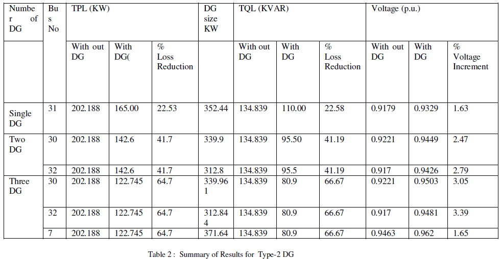
| The proposed algorithm is tested on IEEE38 distribution system. The 38 bus system has 37 sections . The original total real power loss and reactive power loss in the system are 202.188 KW and 134.839 KW respectively. For GA parameters, population size= 100, cross over probability = 0.7 . The maximum number of DG is 3 for each type. One Type-1 DG can reduce total real and reactive power loss by 22.53% and 22.58% respectively. For three Type-1 DGs they can further reduce the loss by 64.7% compared to 38.7% in Type-2 DG. The results are shown in the following tables. |
 |
 |
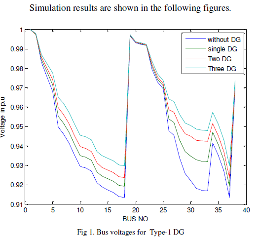 |
| Figure 1 illustrates bus voltages for type-1 DG for all cases i.e. without DG and with single ,two, three DGs. It an be seen that with DG there is much improvement in bus voltages. |
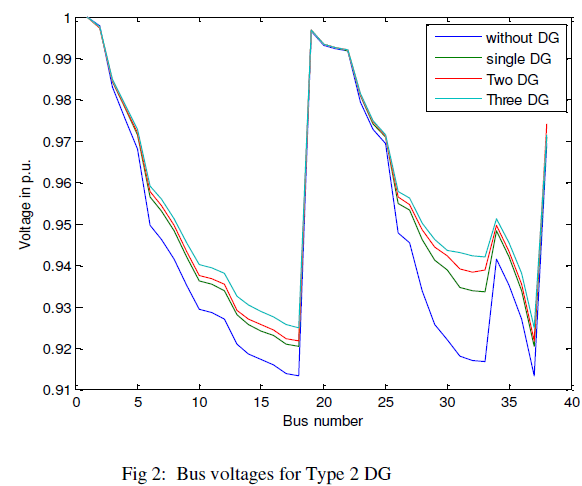 |
| Figure 2 shows bus voltages for type 2 DG. It can be seen that there is more improvement in bus voltages for three DG case as compared to single and two DGs. |
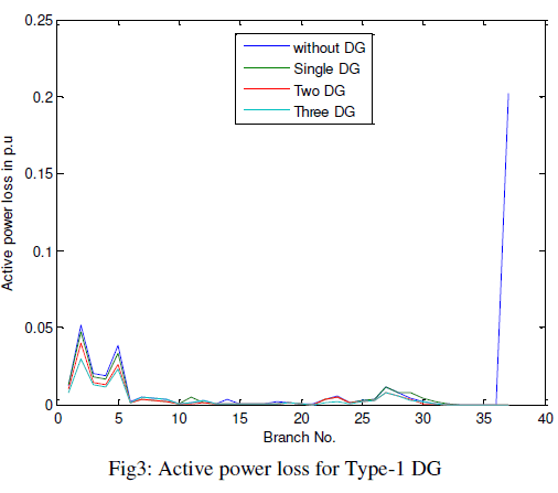 |
| Figure 3 illustrates active power loss for type-1 DG for all cases i.e. with and without DG. It can be seen that without DG the losses are more. With distributed generation the losses are much reduced. The losses are much reduced as compared to type-2 DG. |
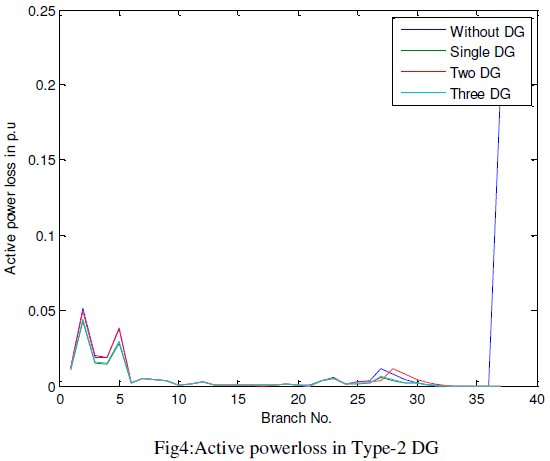 |
| Figure 4 shows active power loss in type-2 DG. With application of DG the losses are reduced. |
CONCLUSION |
| In this paper a genetic algorithm optimization method for optimal placement of multi distributed generation is considered. Using exact loss formula optimal size and location for Type-1 and Type-2 DGs are calculated. The two types of DGs effectively reduced the power loss . It can be seen that voltage profile is improved in the two types of DGs. |
References |
|