International Journal of Advanced Research in Electrical, Electronics and Instrumentation Engineering
ISSN ONLINE(2278-8875) PRINT (2320-3765)
ISSN ONLINE(2278-8875) PRINT (2320-3765)
Girija P K1, Prince A2
|
| Related article at Pubmed, Scholar Google |
Visit for more related articles at International Journal of Advanced Research in Electrical, Electronics and Instrumentation Engineering
Direct Torque Control (DTC) is a method to control the torque in variable frequency drives. This paper describes sensorless DTC of brushless dc (BLDC) motor drive operating in constant torque region under two phase conduction mode to get instantaneous torque control. Sliding Mode Observer (SMO) which is robust to parameter uncertainties is proposed to estimate the phase-to-phase trapezoidal back-EMF for the sensorless operation. This estimated back-EMF is used to deduce the rotor position and the angular velocity of the rotor. And instantaneous electromagnetic torque can be calculated by the product of back-EMF and current.In this paper the effectiveness of sliding mode observer with signum and saturation functions for DTC scheme is investigated.
Keywords |
| Brushless dc motor, Direct torque control, non-sinusoidal back-EMF, Sliding mode observer, two-phase conduction |
INTRODUCTION |
| Now a day the demand of BLDC motor increases due to their high efficiency, higher torque and power density, lower cost, simpler structure, better controllability and large torque to inertia ratio compared to brushless AC motors. So they are used in many domestic and industrial applications ranging from servo to traction drives. A BLDC motor is an insideout DC commutator motor with the mechanical commutator replaced by an electronic switching converter. The most popular way to control a BLDC motor is via voltage –source current-controlled inverters. The inverter must supply a rectangular current waveform whose magnitude is proportional to the motor’s shaft torque. The back-EMF waveform of a BLDC motor is trapezoidal shape due to the concentrated winding. In this paper BLDC with 120º conduction mode is proposed, that means only two-phase conduct at any instant of time. BLDC motor fed by two-phase conduction has higher power/weight and torque/current ratios [1]. Ideally a BLDC motor supplied with rectangular 120º elec. Phase currents produce a trapezoidal back-EMF waveform whose amplitude is constant over >120º elec. will result a ripple free torque. However, in a practical BLDC drive torque pulsation arise due to the deviation of back-EMF waveform from the ideal. |
| In DTC scheme, the torque command obtained from two level hysteresis controller by comparing the estimated electromagnetic torque with their reference value which is obtained from speed error. For the control, voltage vector is selected from a look-up table which depends on rotor flux vector position and the torque error to reduce switching frequency and torque ripple in commutation region [2]. Hall effect sensors are usually used as position sensors to know the position of commutation points. Normally these sensors are mounted on the stator with 120º apart. These sensors increase the cost, size and weight of the motor and reduce the reliability of the total system. To overcome these problems, instead of using position sensors, the sensorless method has been developed to estimate the position and velocity of the rotor from the estimate of phase-to-phase back-EMF using sliding mode observer.Sliding mode observer is a non-linear high gain observer has the ability to bring co-ordinates of the estimator error dynamics to zero in finite time. The stability of the proposed SMO was verified using Lyapunov method to determine the observer gain. The proposed observer is easy to design and has robustness against design parameters [2]-[7]. |
| In this paper, DTC scheme in the constant torque region under two-phase conduction based on sliding mode observer with signum and saturation functions for back-EMF estimation is proposed. Under two-phase conduction, the amplitude of stator flux linkage cannot easily be controlled due to sharp changes and the curved shape of the flux vector locus between two consecutive commutation points. By ignoring the flux control in the constant torque region faster torque response can be achieved. |
MATHEMATICAL MODEL OF BLDC MOTOR |
| Three phase star connected BLDC motor can be described by the following equations, |
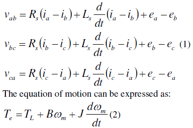 |
| Where v , i and e denote the phase-to-phase voltage, phase current and back-emf respectively in the three phase a, b and c. Rs and Ls denote the line-to-line resistance and inductance of stator winding. Te is the electromagnetic generated torque, TL is the load torque, B is the friction coefficient, J is the polar moment of inertia and m ïÃÂ÷ is the angular velocity of rotor [3],[4]. |
DIRECT TORQUE CONTROL OF BLDC MOTOR |
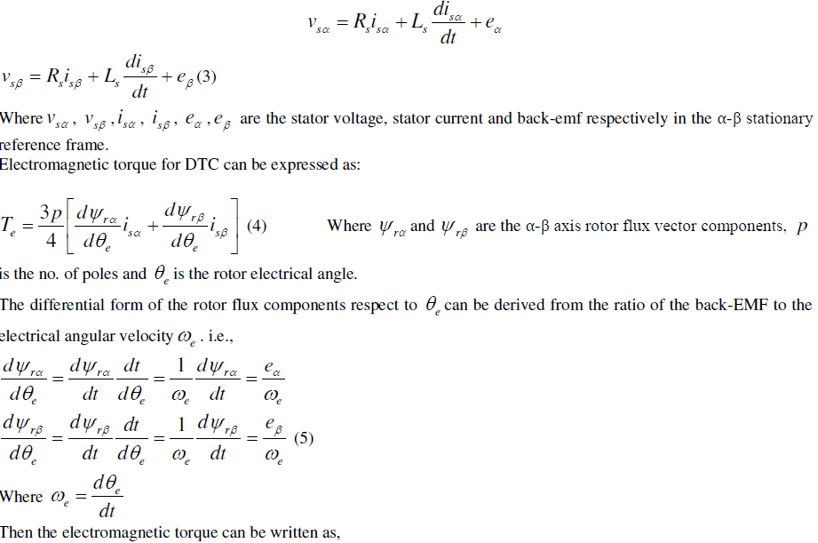
| Transforming the state equation of BLDC motor in α-β stationary reference frame can be written as: |
 |
 |
| Rotor angular velocity for the electromagnetic torque calculation can be obtained from the estimate of sliding mode observer. |
| For the direct torque control, a switching pattern of inverter is selected according to the output of hysteresis controller and the flux vector position. |
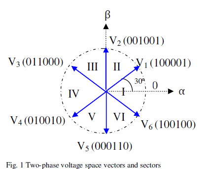 |
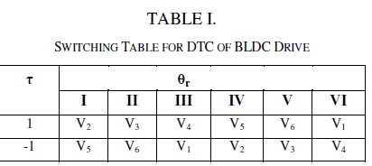
| Fig. 1 shows the six voltage vectors and the sectors. The proper voltage vector, Vi for DTC scheme is selected from the switching table as shown in Table. I. τ denotes the output of hysteresis controller and the sector is denoted as θr. If the reference torque greater than the actual torque, within the hysteresis band limit, the output of the hysteresis controller is defined as τ=1 otherwise τ= -1, out of the six voltage vector, the proper voltage vector for inverter is selected based on the switching table. |
 |
ROTOR FLUX OBSERVER |
| Using rotor flux observer, the rotor flux vector components for (5) can be calculated, |
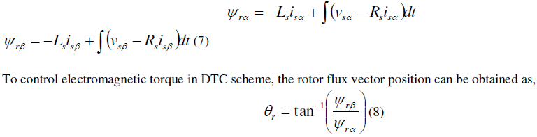 |
SLIDING MODE OBSERVER |
| Sliding mode observer is used for the phase-to-phase back-EMF estimation accurately. |
| Sliding mode observer is proposed as: |
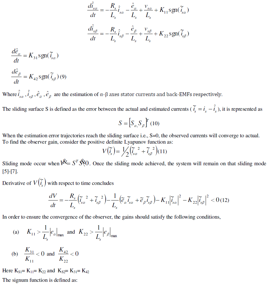 |
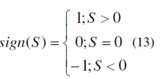 |
| To decrease chattering effect, the signum function in (14) is replaced with saturation function. Saturation function is defined as: |
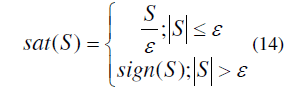 |
| Where is the sliding surface band. |
| In order to reduce the pure integrator influence in the back-EMF estimation, a PI controller is used in this observer [2]. |
ROTOR POSITION AND SPEED ESTIMATION |
| The detection of the six rotor positions (θr) for the proper commutation of a BLDC motor can be easily determined from the estimated back-EMFs in the α-β stationary reference frame [5]-[7]. The estimated rotor position as follows, |
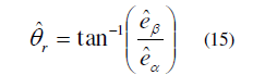 |
| The back-EMFs signals contain the rotor speed information. In order to estimate the instantaneous rotor angular velocity, the following mathematical relation is considered. |
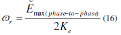 |
| Where, max( phase to phase) E is the amplitude of phase-to-phase back-EMFs and e K is the back-EMF constant [4]. |
 |
RESULT AND DISCUSSION |
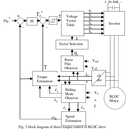
| The overall block diagram of sensorless direct torque control of BLDC drive is shown in fig. 2 was simulated by MATLAB/Simulink. |
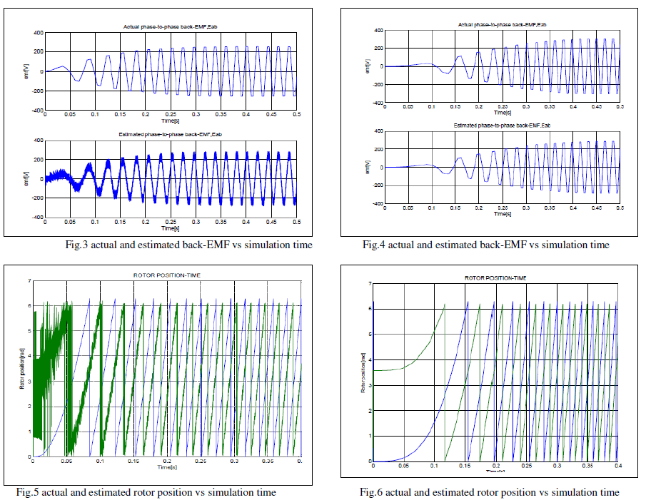
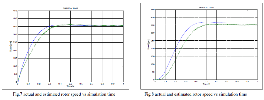
| The actual and estimated âÃÂú-β stationary reference frame phase-to-phase back-EMF, Eab using signum and saturation functions are shown in Fig.3 and Fig.4 respectively. When sliding mode observer with signum function is implemented to estimate the back-EMF of BLDC motor the resulted graph has chattering due to the highly discontinuous nature of the signum function. In order to reduce the chattering, instead of signum function, saturation is given. Then it is observed that the chattering is reduced to great extent. |
| Fig.5 and Fig.6 shows the actual and estimated rotor position using SMO with signum and saturation functions respectively. In fig.5 the estimated rotor position shows the effect of chattering problem. When the saturation function used as a control signal in SMO, the effect of chattering considerably reduced which is shown in Fig.6. The above graphs show a phase delay from the actual rotor position because of the introduction of low pass filter used in the rotor position estimator |
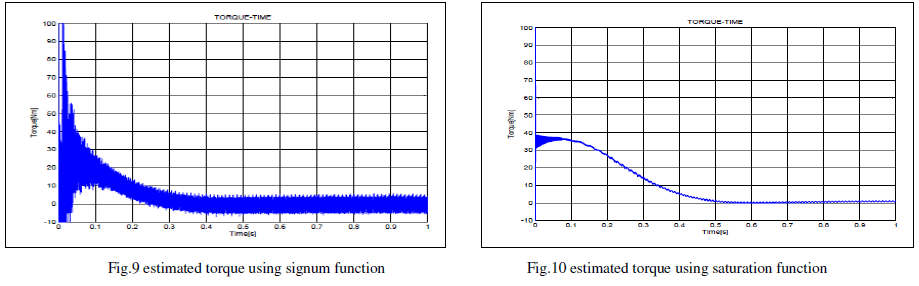
| Fig.7 and Fig.8 shows the actual and estimated rotor speed. When the reference speed of 350rpm was given, the estimated speed tracks the actual speed which is shown in fig.7.fig.8 shows the speed response of SMO with saturation function as control signal; the estimated speed reaches its reference value very quickly. |
 |
 |
| The estimated electromagnetic torque for DTC scheme with signum and saturation functions are shown in fig.9 and fig.10 respectively. By comparing these results it is observed that commutation torque ripple is reduced to great extent by the application of saturation function as the control signal. |
 |
| From the analysis of these results, it is shown that the estimated outputs are accurate. However there is a problem of chattering effect in the estimated waveforms. By neglecting that effect of chattering, sliding mode observer is a very good sensorless method for the estimation of phase-to-phase back-EMFs, rotor position and angular velocity. |
CONCLUSION |
| In this paper, an observer based sensorless direct torque control of brushless DC motor is developed.Using electromagnetic torque error and rotor flux vector position proper voltage vector for inverter switching was selected from look-up table to reduce the torque error within a predefined hysteresis band limit. The performance of SMO with signum and saturation functions for the electromagnetic torque estimation, rotor speed and position estimation and estimation of back-EMFs are verified under DTC scheme. Simulation results shows SMO with saturation function has better speed response, reduced torque ripple and the less effect of chattering in the estimation of rotor position and back-EMF. |
| In sliding mode control, there is a problem with chattering effect due to the presence of switching imperfections, switching time delays and discontinuity in control. In my future work, I plan to replace the discontinuous control functions such as signum andsaturation functions with a continuous sigmoid function and compare the effect of chattering. |
References |
|