ISSN ONLINE(2278-8875) PRINT (2320-3765)
ISSN ONLINE(2278-8875) PRINT (2320-3765)
A.Prasad1, N. Deepika Rani2, N. Balasubrahmanyam3, G. Tirumala Rao4
|
| Related article at Pubmed, Scholar Google |
Visit for more related articles at International Journal of Advanced Research in Electrical, Electronics and Instrumentation Engineering
In modern wireless communication system one of the criteria is control over the antenna beam pattern. Antenna array provides better control over the beam pattern and provides flexibility of scanning in the required direction. The important parameter for consideration in array is spacing between elements. As the spacing between elements is increased beyond half wavelength, the steerability from broadside will significantly reduce due to appearance of grating lobe. In this paper a model of thinned aperiodic linear phased arrays is presented. Differential Evolution algorithm is used for synthesizing the performance of peak side lobe levels
Keywords |
| Antenna arrays, Differential Evolution algorithm, Driving point impedance, Scan angle, thinned aperiodic arrays |
INTRODUCTION |
| The traditional way of creating linear thinned array is by exciting a number of elements in a uniform spaced linear array. The first thinned array was created by removing elements randomly or by trial and error ÃÂÞÃâÃËÃÂøÃÂñÃÂúÃÂð! ÃÂÃËÃâÃÂÃâÃâÃÂþÃâÃâ¡ÃÂýÃÂøÃÂú ÃâÃÂÃâÃÂÃâÃâ¹ÃÂûÃÂúÃÂø ÃÂýÃÂõ ÃÂýÃÂðÃÂùÃÂôÃÂõÃÂý., ÃÂÞÃâÃËÃÂøÃÂñÃÂúÃÂð! ÃÂÃËÃâÃÂÃâÃâÃÂþÃâÃâ¡ÃÂýÃÂøÃÂú ÃâÃÂÃâÃÂÃâÃâ¹ÃÂûÃÂúÃÂø ÃÂýÃÂõ ÃÂýÃÂðÃÂùÃÂôÃÂõÃÂý. . The problem with this arbitrary technique was poor side lobe suppression. This is due to the non-optimal locations of radiating elements. The recent work in thinned arrays made use of different optimization algorithms to remove elements in such a way to have minimum peak side lobe level. Most work on thinning arrays is concentrated only in optimizing an array with low side lobe levels at broadside. As these arrays are scanned a small angle away from broadside, grating lobe appears ÃÂÞÃâÃËÃÂøÃÂñÃÂúÃÂð! ÃÂÃËÃâÃÂÃâÃâÃÂþÃâÃâ¡ÃÂýÃÂøÃÂú ÃâÃÂÃâÃÂÃâÃâ¹ÃÂûÃÂúÃÂø ÃÂýÃÂõ ÃÂýÃÂðÃÂùÃÂôÃÂõÃÂý., ÃÂÞÃâÃËÃÂøÃÂñÃÂúÃÂð! ÃÂÃËÃâÃÂÃâÃâÃÂþÃâÃâ¡ÃÂýÃÂøÃÂú ÃâÃÂÃâÃÂÃâÃâ¹ÃÂûÃÂúÃÂø ÃÂýÃÂõ ÃÂýÃÂðÃÂùÃÂôÃÂõÃÂý.. This paper presents a model of thinned aperiodic linear phased arrays for various scan angles. DE algorithm is used for synthesizing the performance of peak side lobe levels. The optimization process causes the perturbation added to each element in periodic array to create an aperiodic array. |
ANTENNA ARRAY CONFIGURATION |
| For a single element antenna the dimension of element gives the aperture. For linear array, the aperture is decided by the distance between two farthest elements. With the help of antenna arrays pattern control and beam scanning are possible. A basic array geometry and coordinate system is shown in Fig. 1. |
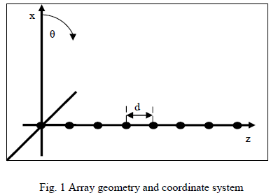 |
| N elements are arranged in a straight line along z-axis with uniform element spacing „dâÃâ¬ÃŸ. If the elements in the array are isotropic sources, then the radiation pattern of array is described by the array factor as ÃÂÞÃâÃËÃÂøÃÂñÃÂúÃÂð! ÃÂÃËÃâÃÂÃâÃâÃÂþÃâÃâ¡ÃÂýÃÂøÃÂú ÃâÃÂÃâÃÂÃâÃâ¹ÃÂûÃÂúÃÂø ÃÂýÃÂõ ÃÂýÃÂðÃÂùÃÂôÃÂõÃÂý. |
 |
| Where AF is array factor, k is free space wave number, θ is the angle measured from broadside, θ0 is the beam scan angle from broad side and In is the excitation current of nth element in the array and ïÿýïÿýïÿýïÿý is distance of nth element from origin. For uniform array |
 |
SCAN ANGLE |
| The maximum scan angle for uniform array without grating lobe is given by |
 |
 |
INCREASED STEERABILITY USING THINNED APERIODIC PHASED ARRAYS |
| The maximum scan angle in thinned periodic array is limited by grating lobe. These grating lobes are the result of superposition of the element patterns when the array is steered to an angle greater than that given by eq. (3). To overcome this, the element locations in periodic array can be perturbed in such a way so that the pattern from each element is in phase. After perturbation, the element locations are given as |
 |
| Where δdn is the perturbation. |
| Fig. 2 shows the thinned aperiodic phased array (grey elements) obtained by adding a perturbation δdn to the position of each element in the periodic array (black elements). An N element array require N separate positional perturbations. The solution space of this problem is very large, so we need optimization called Differential Evolution (DE). |
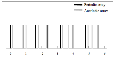 |
| Fig. 2 The geometry of thinned aperiodic array (grey elements) created by adding perturbations to the thinned periodic array (black elements) |
| In this paper the optimization process is developed based on equation (4) for generating arrays that have radiation pattern with reduced grating lobe. The perturbation limits consider for aperiodic model is -0.4λ≤ δdn ≤ +0.4λ. |
DIFFERENTIAL EVOLUTION |
| DE algorithm is a global search technique which was described in ÃÂÞÃâÃËÃÂøÃÂñÃÂúÃÂð! ÃÂÃËÃâÃÂÃâÃâÃÂþÃâÃâ¡ÃÂýÃÂøÃÂú ÃâÃÂÃâÃÂÃâÃâ¹ÃÂûÃÂúÃÂø ÃÂýÃÂõ ÃÂýÃÂðÃÂùÃÂôÃÂõÃÂý., ÃÂÞÃâÃËÃÂøÃÂñÃÂúÃÂð! ÃÂÃËÃâÃÂÃâÃâÃÂþÃâÃâ¡ÃÂýÃÂøÃÂú ÃâÃÂÃâÃÂÃâÃâ¹ÃÂûÃÂúÃÂø ÃÂýÃÂõ ÃÂýÃÂðÃÂùÃÂôÃÂõÃÂý.. |
| DE notations used in this paper are |
| Ps = size of population, t = no. of generations, F = Mutation factor, CR = cross over rate, Xi(t) = target vector. |
| The initialization of population is done after lower and upper bound for parameters were specified. In D- dimensional search space, the initial population is given by |
| Where Xi(t) is target vector and is given by |
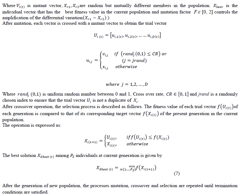
| After the initialization, the evaluation of the fitness of each population is done with the help of Fitness Function. After fitness function evaluation, the best crossover solution is used by the mutant vector, given by |
 |
OPTIMIZATION RESULTS |
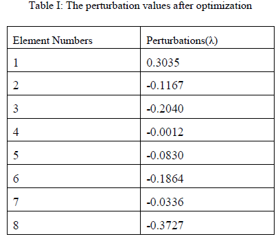
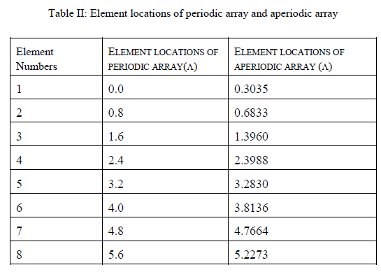
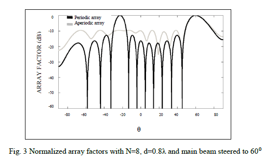
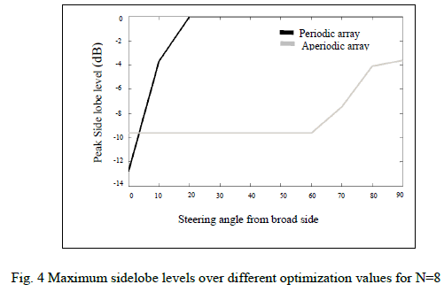
| The optimization procedure above was performed on an eight element array with a uniform spacing of 0.8λ with uniform current excitation. From equation (3) it can be seen that a thinned periodic phased array with this spacing has a maximum scan angle of 14.50 from broad side without grating lobes. In this paper, we consider main beam steered to 600 from broadside for optimization. The fitness function is peak side lobe level. Fig. 3 shows the result of normalized array factor obtained after DE algorithm in comparison to that of periodic array when main beam steered to 600 from broadside. The DE algorithm reduces the grating lobes with pattern having maximum side lobe level of -9.634 dB. So, the optimized array having steerability 00 to 600 from broadside having maximum side lobe level is -9.634 dB. Table-1 shows the perturbation values after optimization and Table-2 shows the element locations of periodic array and optimized aperiodic array (λ). We increase the scan angle up to 900, there is no grating lobes appeared. Fig. 4 shows the maximum side lobe level for aperiodic array in comparison to periodic array when main beam steered up to 900 from broadside .so there is complete scan range of 900 from broadside. |
 |
 |
 |
 |
CONCLUSIONS |
| Using optimization technique the complete scan range of 90° from broad side can be achieved with SLL under specified limits. Varying the spacing between elements causes the change in mutual coupling environment, which has impact on the driving point impedance. |
References |
|