ISSN ONLINE(2278-8875) PRINT (2320-3765)
ISSN ONLINE(2278-8875) PRINT (2320-3765)
Kishore Kumar S1, Dr. R. Senthil Kumar 2
|
| Related article at Pubmed, Scholar Google |
Visit for more related articles at International Journal of Advanced Research in Electrical, Electronics and Instrumentation Engineering
The greatest threat to national security is “Terrorism” infiltrating through borders. In critical border areas such as Kashmir and Bangladesh regular forces or even satellites cannot monitor these intruding terrorists as the area monitored is quite large and quite complex. This project provides an innovative and effective solution to this problem. The project aim is to design a next generation intelligent ultra-small dust like wireless sensor motes which has multiple onboard sensors and a controller, which has the ability to detect an enemy intrusion across borders and battlefields. Thousands of these smart dust motes can be deployed within a large area in a few hours by one or two men. These motes can form a network on its own among them, are small in size, rapidly deployable, have wireless connection to outside world. They detect the intrusion and classify it into vehicles or individuals and groups. Onboard hardware include a variety of sensors for vibration/seismic, magnetic, acoustic and thermal signature recognition, an microcontroller for processing these sensor values and a radio transceiver for communication over a wireless network. The system (Smart Dust) process the sensor readings, classify the targets and the tracking history can be viewed in the Graphics LCD display attached in the central monitoring unit. The central monitoring node acts as the parent node in a peer to peer wireless network model. The dust motes communicate with central parent node using wireless radio network.
Keywords |
| Dust Motes, Enemy Intrusion Detection, Sensors, Wireless Sensor Network |
INTRODUCTION |
| Intrusion detection is a major problem in this application.Timely detection of intrusion is the very sensitive part in detecting the intrusion. When intrusion happens in large terrain or rough areas it is hard to detect, since surveying those areas through men becomes a difficult task. Intrusion detection in the given application normally deals with the detection of objects and classifies it in to human or vehicle or groups and track the enemy intrusion. Enemy intrusion is identified, classified and tracked by using the next generation intelligent ultra-small dust like wireless sensor motes which has multiple onboard sensors and a controller, which has the ability to detect an enemy intrusion across borders and battlefields. These smart dust motes are the collection of sensors and a controller. |
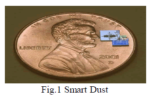
| Thousands of these smart dust motes can be deployed across the border in a few hours by one or two men. These motes are small in size as shown in Fig 1, are rapidly deployable and they form a network on its own and give the result to the outside world through wireless connection. Onboard hardware consists of variety of sensors such as vibration/seismic, magnetic, acoustic and thermal signature recognition, and microcontroller for processing these sensor values and a radio transceiver for communication over a wireless network. The mote consists of all this hardware is called the dust mote. The parent mote (controlling node) consists of a controller and a graphics display through which the tracking history can be viewed. |
 |
| The central monitoring node acts as a parent node and is connected in a peer to peer wireless network model. So that if there is a fault/mote is not working we can identify it and rectify it easily as all motes are connected in peer to peer network. |
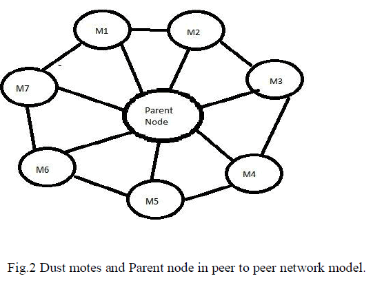 |
| As shown in Fig 2. M1, M2, M3, M4, M5, M6, M7 represents the motes which consist of the different sensors and the controller, which detects and classify the intrusion and sends the details to the parent node through wireless communication. |
II. DISCUSSION |
| The aim of this paper is to implement a border intrusion detection system using small and cheap sensor nodes which can be left unattended and are difficult to detect because of their size. We are not using large expensive equipment for monitoring which can cover a larger area for monitoring because if this equipment is disabled, intentionally or unintentionally, it will result in data unavailability. |
| One of the main drawbacks pointed out in sensor networks is battery power. The need to frequently change batteries and the corresponding manpower required for this task is a big deterrent to the usage of sensor networks. Recent advances in the field of powering sensor nodes suggest the idea of using a mobile-host based wireless energy transmission system to provide power. The mobile host has the capability of wirelessly transmitting energy to sensor nodes on an as-needed basis. The wirelessly transmitted microwave energy is captured by a receiving antenna, transformed into DC power by a rectifying circuit, and stored in a storage medium to provide the required energy to the sensor node. Also, energy for the sensor nodes can be scavenged. Some long-lasting sources of sensor power are: solar power, temperature gradient, vibrations and pressure variations. The above mentioned methods will be extremely helpful in solving the critical issue of power in the wireless sensors domain. |
| Using sensor networks for border monitoring has a plus point that the entire border area does not have to be necessarily covered. The terrain can be helpful in reducing cost since some areas will be inaccessible and hence sensor nodes need not be spread in these areas. Even though building fences along the entire border is an option, there are several difficulties associated with it. For example, after building a fence it is necessary to ensure that the fence is not broken at any place. Using electric fences would be an enormous overhead. Moreover, if a fence is constructed, it will have to be constructed through and through. Sensor networks have an advantage here as terrain can be assistive and nodes need not be placed everywhere. |
| Another concern while considering the use of sensor nodes is how the nodes will be placed. If sensors are air dropped then the number of sensors required will be much higher. This issue can be addressed by deploying the sensors in a few hours by one or two men. In the terrain which is accessible, the nodes can be placed manually by travelling short distances in a helicopter (if roads are nonexistent). If the terrain is difficult to access, then air dropping is an option or more advanced techniques like using laser guns to shoot and place the sensors in the ground may also be used. |
III. RELATED WORK |
| Previous research has been done in the area of border intrusion detection; where Images from cameras are taken near the border can be processed to detect border intrusion. Optical fiber cables can be buried under the ground near the border and optical pulses sent down in to the ground due to the movement of the intruder can be monitored and processed to detect intrusion. But the cost of deployment and maintenance of video cameras or optical fiber cable is high and hence these approaches may not be feasible for monitoring the borders which are too large like the Indo-China border. |
| Research has been done on how to use small and low cost wireless sensor motes for monitoring different environment settings and places of interest for example, habitat monitoring, monitoring volcanic activity etc. Research is also being done on how to effectively deploy sensors in order to achieve maximum coverage of an area. Sensors have also been used for monitoring borders but usually the sensors used are expensive and there is a requirement of an observer who can analyze the data collected by the sensors and make a decision. |
| In this project we use variety of sensor including the controller together called as motes are used to detect, classify and track the intrusion happens across border. |
IV. ARCHITECTURE OF SMART DUST NETWORK |
| The system consists of 2 important motes (i) Dust mote, which consists of different sensors and a controller to read the values from the sensor and a transceiver to send those data to the central parent node. (ii) Central Monitor mote, which consists of a wireless transceiver to receive the data that sent from the dust mote, and a LCD display where all the tracking history can be viewed. |
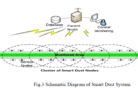 |
| Fig 3. Shows the schematic view of the smart dust system, which contains the dust mote and the central monitor mote. |
V. DESIGN OF HARDWARE |
| The hardware of this system is mainly divided in to two parts. One is the dust mote which consists of different sensors to identify the particular type of intrusion happening in the area. The second one is the central monitor mote which controls all the dust motes and keeps track of the intrusion |
| Fig.4 (a) shows the block diagram of the Dust Mote which consists of several sensors, Arm Cortex-M3 controller and an IEEE 802.15.4 wireless transmitter to send the data’s to the Central Monitor Mote. The different sensors used in Dust Mote are 1. Thermal Sensor Motion 2. Magnetic Sensor 3. Vibration Sensor 4. Acoustic Sensor. |
| The thermal sensor used in Dust Mote is the PIR sensor-Passive Infrared Sensor. PIR sensor is mainly used for human detection. Humans emit some amount of Infrared radiation which is absorbed by PIR to identify the human intrusion. Magnetic Sensor used here is MEMS Magnetometer. This is used to identify the vehicle intrusion and also used as a metal detector. In this project 3-axis magnetometers are used to detect any intrusion. |
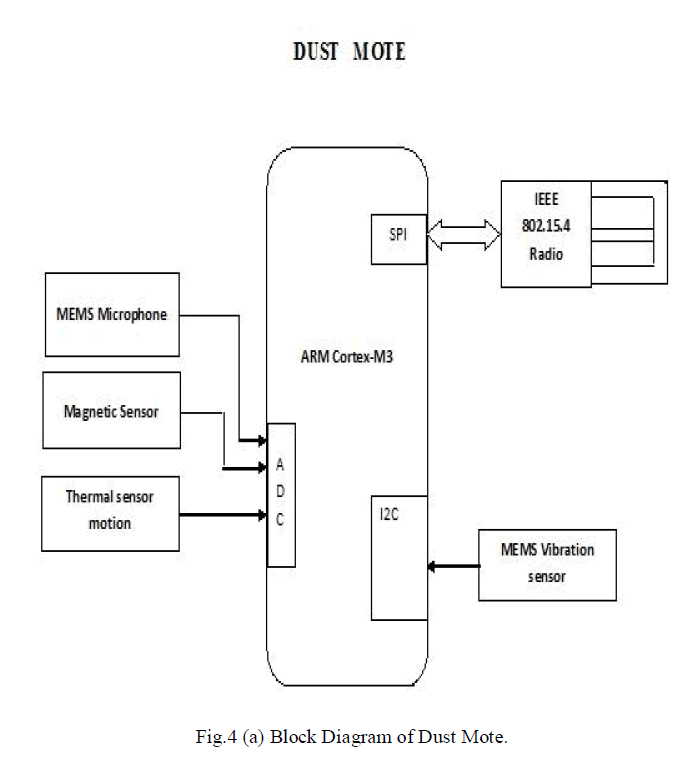 |
| Vibration Sensor used here is MEMS Accelerometer which in turn has the ability to detect vibrations which occurs when group of persons try to intrude or large vehicles run across the border. Acoustic Sensor used to detect acoustic waves in the border. MEMS Microphone is used to detect such small audios. This microphone is used to tap the messages of the enemies in the border. |
| All these sensors values are sent to the microcontroller present in the Dust Mote and the values are read and sent to the Central Parent Mote through wireless communication, So that the Central monitoring mote keeps track of the intrusion history in the display |
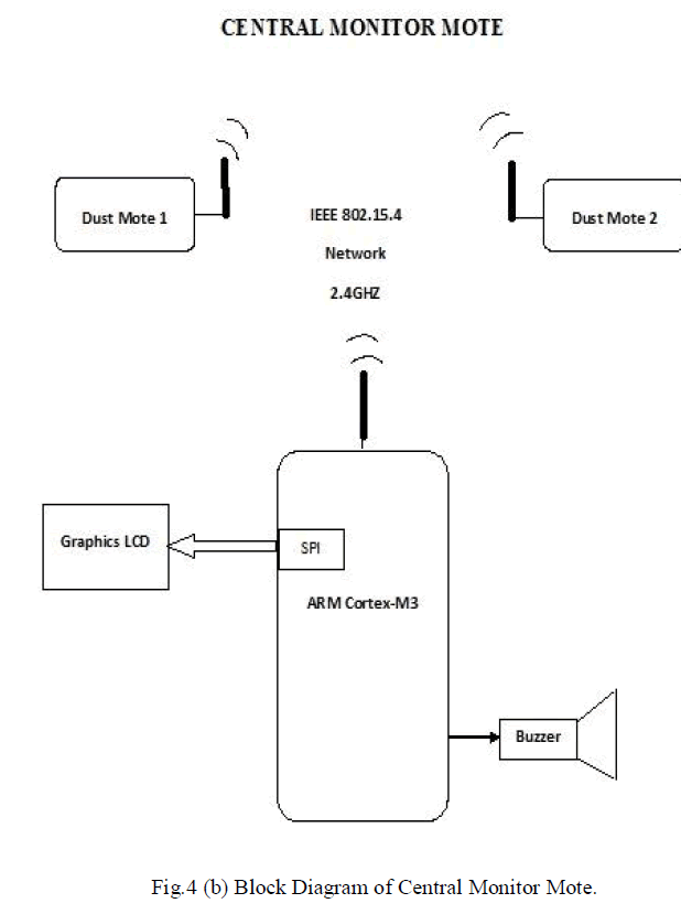
| Fig.4 (b) Illustrates the block diagram of the central monitor mote, which consists of Arm Cortex M3 controller, LCD Display, MiWi transceiver and a buzzer. |
| This central monitor mote receives the data’s which are the sensor values from the dust mote through wireless communication called MiWi and keeps track of the history in the LCD Display. In case of critical situation it raises an alarm through the buzzer connected to the controller to alert the situation. |
 |
| The detailed description about the sensors and the MiWi protocol is given below. |
A. Thermal Sensor |
| Thermal sensor is used to detect the intrusion by the heat generated in the border or across the areas. A Passive Infrared Sensor is used to develop this application. PIR sensor also called Passive Infrared Sensor is used here to detect the intrusion by absorbing the IR emitted from the objects. Every object tends to emit some amount of IR. |
| Another important factor is that the PIR sensor can be easily placed on a wireless sensor node. The application is mainly focused on detecting human Intruders in a secured area. Human body generates heat. IR emitted from human ranges from 8 to 14μm range. The window may be used as a filter, to limit the wavelengths to 8-14 μm, which is closest to the infrared radiation emitted by humans. These values are sent to the Fresnel lens and then it reaches the PIR. |
| The values generated from the PIR sensor is sent to the controller through ADC, since the values generated from PIR sensor are analog values. Once the values are feed to the controller it starts processing the value and send the data to the central monitoring mote. |
B. Magnetic Sensor |
| MEMS Magnetometer is used in this application to measure the strength and the direction of magnetic fields. By calculating the strength of the magnetic field we can determine the intrusion type, whether it is a weapon or a vehicle. These magnetometers are used as metal detectors in this application. They are capable of detecting metals as well as capable of detecting large objects such as Military tank or heavy military vehicle. |
| 3-axis Magnetometer is used here to detect the intrusion all over the border. MEMS Magnetometer is very small in size and can be interfaced very easily with the controller to form the dust mote. The values from the magnetometer are sent to the controller for processing, once processed it is sent to the central monitoring mote for tracking. |
C. Vibration Sensor |
| An accelerometer is used as a vibration sensor in this project. This accelerometer is used to measure vibration and shock. This acceleration is properly measured in terms of g-force. G-force is the gravitational force. |
| MEMS accelerometers are used in this application, since they are small in size and can be easily interfaced as well they are easily deployable. Since they are very small they consume very low power which makes them more efficient comparative to existing system. 3-axis MEMS accelerometer is used here to detect heavy movements in the land areas which happen due to the movement of group of persons or movement of large vehicles. Once detection is identified it is processed in the controller and sent to the control mote via wireless connection. |
D. Acoustic Sensor |
| Acoustic sensor is able to identify acoustic waves. MEMS microphones target all audio applications where small size, high sound quality, reliability and affordability are key requirements. |
| MEMS microphone are designed in industry-unique, innovative plastic packaging that offers slimmer form factors, and outperforms traditional metallic lid devices in durability. Both analog- and digital-input top and bottom port solutions are available. Normally the output from the audio sensor will be an analog value, hence it is processed in the controller through ADC and the processed value is sent to the central monitoring mote for tracking purpose through wireless connection. |
E. MiWi P2P Protocol |
| MiWi P2P is wireless Protocol designed by Microchip is based on IEEE 802.15.4 standard for wireless personal area networks. This protocol is designed for low data transmission rates and short distance and is low-power wireless sensors |
| The protocol provides reliable direct wireless communication through a user friendly programming interface. The MiWi P2P protocol stack supports star and peer-to-peer wireless-network topologies, useful for simple, short-range, wireless node-to-node communication. In this project peer-to-peer wireless network model is used. Additionally, the stack provides sleeping-node, active-scan and energy-detect features while supporting the low-power requirements of battery-operated devices. MiWi protocol works in 2.4 GHz frequency band. |
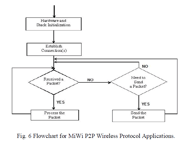
| MRF24J40MA is the wireless transceiver used in both the dust and central monitoring mote to transfer the data’s between them. The flowchart used in MiWi wireless protocol is shown in Fig 6. |
| Initially the sensor’s in the hardware are initialized to detect the enemy intrusion and the connections between the dust mote and the central monitor mote are established. Whenever there is an enemy intrusion the sensors in the dust mote gets triggered and sends the data to the central monitor mote through this connection. |
 |
| The application is developed using Arm Cortex-M3 Controller. LPC1313FBD48 are Arm Cortex based controllers used for high level integration and low power consuming. This controller has the ability to work at 72 MHz frequency, has 32 kb of flash memory and can connect up to 42 general purpose devices within it. |
| Once enemy intrusion is detected, the information from the dust mote is sent and it is received in the central monitoring mote and it is displayed in the LCD connected in the central monitor mote. The tracking history can be stored and can be viewed in the display. The tracking history consists of all intrusions such as Human intrusion, Groups of people, Vehicle intrusion etc. |
| The program is coded in such a way if there is any intrusion then that particular sensor is triggered and the values is given to the ADC to sample the values generated and converts in to digital value. These values are processed in the given controller and the information are sent to the central monitor mode through MiWi protocol. The codes are written in Embedded C language. Initially MiWi is interfaced then, the interfacing of the sensors is done. |
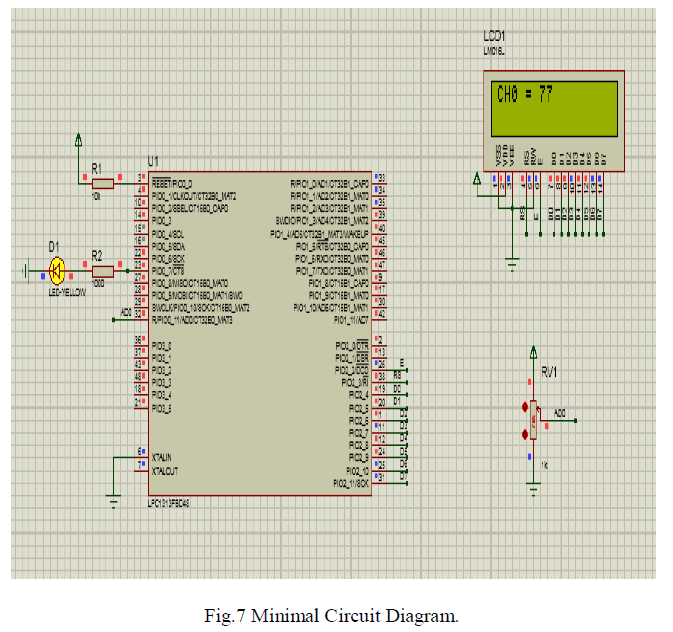
| The minimal circuit diagram is shown in the Fig 7.This circuit shows how the LPC1313FBD48 is interfaced along with the PIR sensor to get the values and it is displayed in the LCD display. |
 |
| Similarly the intrusion readings varies when single and multiple motes are used. Now the reading from single mote is analysed and the approximate value from the motes are given below. |
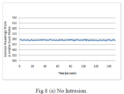 |
| Fig.8 (a) indicates the working condition of the sensor in a single Dust Mote, if there is no intrusion happening in a particular place or area. If there is no intrusion the readings remain constant i.e the predefined value which is set while writing the program. |
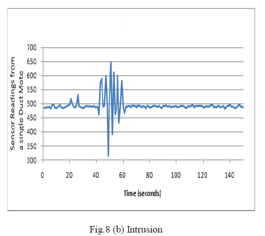 |
| If there is no intrusion then there will be a varying in the reading. The reading depends upon the intrusion type. If a single person intrusion occurs the value in the sensor will be low comparative to the vehicle intrusion. Fig.8 (b) shows the working condition of the sensor in a single Dust Mote if there is an intrusion. |
VII. CONCLUSION AND FUTURE WORK |
| In summary, enemy intrusion is detected by combination of sensors interfaced with the controller in the given application. In this application Thermal Sensor, Vibration Sensor, Magnetic Sensor and Acoustic Sensor are used to detect enemy intrusions like human or group of persons and vehicle intrusion. By using this application, human life can be saved to greater extent, since these motes does the enemy intrusion and tracking job. This application possessed to be of low cost comparative to the earlier technologies. |
| Power consumption becomes a slight concern which can be rectified by using solar cells in the future. As well as more sensors can be interfaced to the controller to do more detection. The size of the Dust Mote can be reduced in a greater manner by reducing the size of the controller of size 10mm can be used to achieve this. |
References |
|