ISSN ONLINE(2278-8875) PRINT (2320-3765)
ISSN ONLINE(2278-8875) PRINT (2320-3765)
Felice Browni I1, Jaffya G.V2
|
| Related article at Pubmed, Scholar Google |
Visit for more related articles at International Journal of Advanced Research in Electrical, Electronics and Instrumentation Engineering
In spite of the improvement of communication link and despite all progress in advanced communication technologies, there are still very few functioning commercial wireless monitoring systems, which are more off-line, and there are still a number of issues to deal with. Therefore, there is a strong need for investigating the possibility of an interactive real-time wireless communication system. In our project a generic real-time wireless communication system was designed and developed for short and long term remote patient monitoring applying wireless protocol.The primary function of this system is to monitor the temperature of the body, heartbeat and blood pressure in the body and sent the collected data to the Doctor via Short Message Service.
Keywords |
| sensor, GSM modem, LED and an LDR, systolic pressure, diastolic pressure, cuff. |
INTRODUCTION |
| Embedded Systems are one of the emerging technologies which are touching every nook and corner of the mind.”It is impossible to live without these embedded gadgets” – says ELECTRONICS magazine. Some severe disease like heart failure, hypotension etc. requires continues monitoring. However the patients are often too early released, owing to the need of hospital bed for another patient on the waiting list, who needs to be hospitalized immediately. |
| One of the primary challenges faced by healthcare authorities is being able to maximize the quality and breadth of healthcare services while controlling costs. As the population ages and demand for services increases, the ability to maintain the quantity and availability of care, while effectively managing financial and human resources, is of critical importance. Use of modern communication technology in this context, is the sole decisive factor that makes such communication system successful. |
DESCRIPTION |
| This monograph discusses the development and application of continuous bio telemetry system. In such a system the biosensor are used to measure the physiological signal such as heart beat, temperature and blood pressure of the patient. The obtained signals are filtered and amplified and transmitted to remote storage server using GSM modem as a base station. The information in the remote storage server can be instantly accessed by doctor or patient’s relative via sms. |
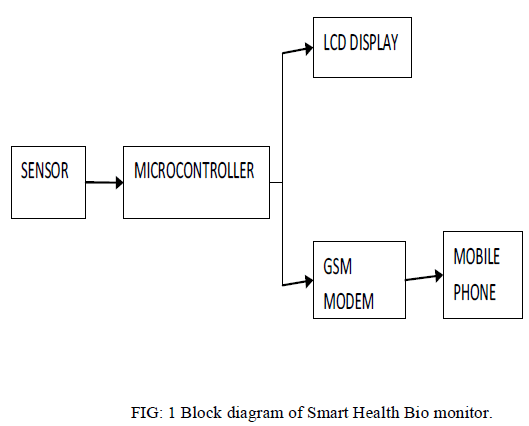 |
| HEARTBEAT SENSOR: This block is used to sense the heartbeat with the help of an LED and an LDR. Continuous light from the LED should fall on the LDR and the finger of the patient is to be placed in between the LED and LDR. The slight variation in the skin due to the heartbeat is read by the LDR. The LDR output is fed to an operational amplifier to the digital level (0 and 5) which is fed to the microcontroller. |
| TEMPERATURESENSOR:This sensor is used to read the temperature of the patient’s body. This is done by using a temperature sensor Ic which incorporates a temperature sensor, an analog to digital converter and a serial converter. |
| PRESSURE SENSOR: This sensor is used to measure the blood pressure of the patient’s body. The systolic pressure which is under the arteries as the heart contracts and diastolic pressure which is under the arteries as the heart expands can be detected using a cuff |
| GSM MODEM: GSM Modem provides full functional capability to Serial devices to send SMS and Data over GSM Network. The product is available as Board Level or enclosed in Metal Box. The Board Level product can be integrated in to Various Serial devices in providing them SMS and Data capability and provide serial port connection. The GSM Modem supports popular "AT" command set that users can develop applications quickly. |
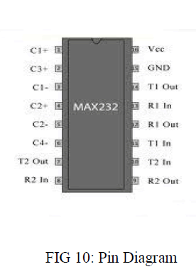
| MAX232:The MAX232 is integratedcircuits that convert signals from an RS-232 serial port to signals suitable for use in TTL compatible digital logic circuits. The MAX232 is a dual driver/receiver and typically converts the RX, TX, CTS and RTS signals. |
HEART BEAT MONITORING |
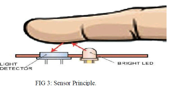
| The sensor used for Heart beat monitoring is LED/LDR Sensor. Heart beat sensor is designed to give digital output of heart beat when a finger is placed on it. When the heart beat detector is working, the beat LED flashes in unison with each heart beat. This digital output can be connected to microcontroller directly to measure the Beats per Minute (BPM) rate. It works on the principle of light modulation by blood flow through finger at each pulse. |
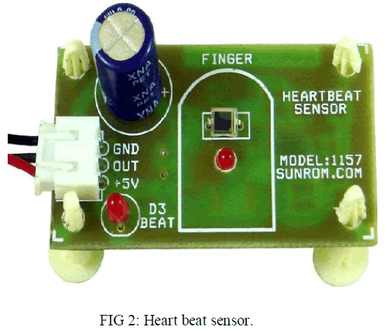 |
| Connect regulated DC power supply of 5 Volts. Black wire is Ground, Next middle wire is Brown which is the output and Red wire is positive supply. These wires are also marked on PCB.To test sensor you only need to power the sensor by connecting two wires +5V and GND. The output wire as it is. When Beat LED is off the output is at 0V.Put finger on the marked position, and you can view the beat LED blinking on each heart beat. The output is active high for each beat and can be given directly to microcontroller for interfacing applications. This sensor consists of a super bright red LED and light detector. The LED needs to be super bright as the maximum light must pass spread in finger and detected by detector. Now, when the heart pumps a pulse of blood vessels, the finger becomes slightly more opaque and so less light reached the detector. With each heart pulse the detector signal varies. This variation is converted to electrical pulse. This signal is amplified and triggered through an amplifier which outputs +5V logic level signal. The output signal is also indicated by a LED which blinks on each heart beat. |
 |
| The features are Heart beat indication by LED, instant output digital signal for directly connecting to microcontroller, Compact Size, Working Voltage +5V DC.The applications are digital Heart Rate monitor, Patient Monitoring System, bio-Feedback control of robotics and applications. The output signal of heartbeat sensor. If the finger is placed on the sensor the LED will be ON i.e., it shows the higher level and lower level. The higher level denotes the pumping of heart pulse through the blood vessels and the lower level denotes the relaxation of heart. If the finger is not placed in the sensor the LED will be OFF i.e., it shows no beat detected |
TEMPERATURE SENSOR |
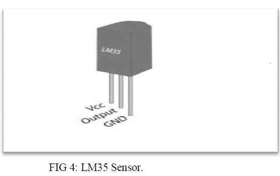
| LM35 is a precision IC temperature sensor with its output proportional to the temperature (in oC). The sensor circuitry is sealed and therefore it is not subjected to oxidation and other processes. With LM35, temperature can be measured more accurately than with a thermistor. It also possesses low self-heating and does not cause more than 0.1oC temperature rise in still air. |
| The operating temperature ranges from -55oC to 150oC. The output voltage varies from 10mV in response to every oC rise/fall in ambient temperature, i.e., its scale factor is 0.01V/oC. The LM35 series that is used in this project is a precision centigrade temperature sensor, which has an analog output voltage. It has a range of -55oC to +150oC and an accuracy of ±0.5oC. The output voltage is 10mV/oC.The output voltage is given to PIC16f877a which consist of inbuilt Analog to digital convertor . The temperature is displayed on an LCD and also sends SMS through GSM module. In this example the thermometer has a range of 0oC to 40oC and a resolution of 0.5oC. If you want to read out in Fahrenheit you can be used the LM34. The LM53 can be applied easily in the same way as other integratedcircuit temperature sensors. It can be glued or cemented to a surface and its temperature will be within about 0.01oC of the surface temperature.LM35 presumes that the ambient air temperature is almost the same as the surface temperature. If the air temperature were much higher or lower than the surface temperature, the actual temperature of the LM35 die would be at an intermediate temperature between the surface temperature and the air temperature. This is especially true for the TO-92 plastic package, where the copper leads are the principal thermal path to carry heat into the device, so its temperature might be closer to the air temperature than to the surface temperature. |
| To minimize this problem, be sure that the wiring to the LM35, as it leaves the device, is held at the same temperature as the surface of interest. The easiest way to do this is to cover up these wires with a bead of epoxy which will insure that the leads and wires are all at the same temperature as the surface, and that the LM35 die’s temperature will not be affected by the air temperature. |
 |
| Some of the applications of LM 35 is given by oven controllers, remote temperature sensing. The advantages of LM 35 is given by accurate measurement than thermistor,the sensor circuitry is sealed and not subjected to oxidation etc...produce higher output voltage than thermocouples, no need for any amplification, it is more reliable and has less power consumption. |
BLOOD PRESSURE SENSOR |
| The sensor used here is Oscillometric Pressure sensor. The blood pressure sensor typically uses a thin diaphragm as one plate of capacitor. Applied pressure causes the diaphragm to deflect and the capacitance to change. This change may or may not be linear and is typically in this order of several Pico farads of order 50-100pF. If the dielectric constant of the material between the plates isn’t kept constant, errors may result. Capacitive absolute pressure with the vacuum between the plates is ideal in this respect. Because the capacitance of this sensor depends only on, physical parameters, Sensors with good performance can be constructed using materials with low coefficient of thermal expansion. Since the device has to be fairly large to obtain an unstable signal, frequency response may be a problem in some applications. Also low-pressure capacitive sensors exhibit acceleration and vibration sensitivity due to necessity. |
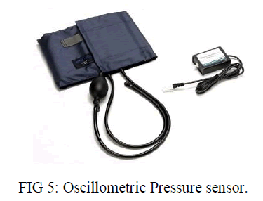 |
| In an automatic oscillometric blood pressure monitor compromising a pressurized cuff, means for inflating and deflating said cuff, means for measuring arterial pressure oscillation complexes through measurement to time varying pressure within said cuff, and means determining a patient’s blood pressure predetermined intervals by instructing said inflating and deflating means to inflate said cuff about an artery of the patient until said cuff is at a pressure level above the patient’s systolic blood pressure and to deflate said cuff by predetermined pressure decrements, by searching for arterial pressure oscillation complexes at each pressure level, and by determining from said arterial pressure oscillation complexes an oscillation envelope of a patient, a method of monitoring a patient’s blood pressure comprising the steps of: determine the patient’s heart rate without inflating said cuff; Monitoring variation in said heart rate; Correlating variation in said heart rate with variation in the patient’s blood pressure, and initiating a blood pressure determination by said oscillometric blood pressure monitor prior to the expiration of any of said predetermined intervals if variation in the patient’s heart rate correlate to a predetermined percentage change in the patient’s blood pressure. |
GSM MODEM |
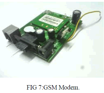
| GSM Modem provides full functional capability to Serial devices to send SMS and Data over GSM Network. The product is available as Board Level or enclosed in Metal Box. The Board Level product can be integrated in to Various Serial devices in providing them SMS and Data capability and the provide serial port connection. The GSM Modem supports popular "AT" command set that users can develop applications quickly. The product has SIM Card holder to which activated SIM card is inserted for normal use. The power to this unit can be given from UPS to provide uninterrupted operation. This product provides great feasibility for Devices in remote location to stay connected which otherwise would not have been possible where telephone lines do not exist. |
 |
CIRCUIT DESCRIPTION |
| When the 5V DC power supply is given to the PIC controller, the glowing of power LED indicates whether the circuit is in working condition or not. The PIC controller have five ports such as Port A, Port B, Port C, Port D and Port |
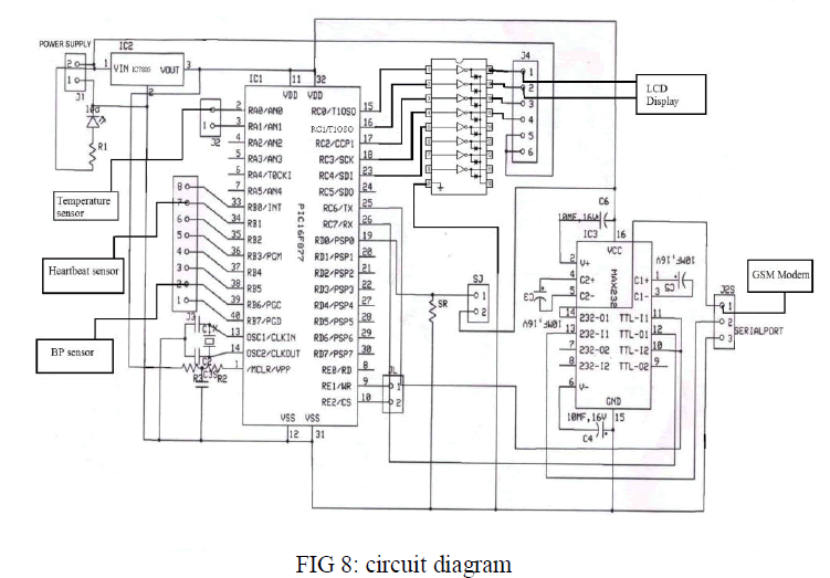 |
| E. In Port A, the temperature sensor is connected. The output of the temperature sensor is analog. Here in PIC16F877a the ADC pins are available and it is inbuilt in this controller.RA0-RA5 represents the ADC pins. In Port B, both the heartbeat sensor and blood pressure sensor is connected. These two sensors are connected in any other ports except Port A. In Port C, both LCD display and GSM modem are connected. GSM modem is interfaced at the serial communication Port 25 and 26. This interfacing is done with the help of MAX232 by using RS232 cable. The clock pulse is given to the microcontroller by using crystal oscillator, According to that clock pulse the microcontroller will operate. The LCD display requires 12V supply so by using ULN2803 IC the 5V is regulated into 12V DC. |
| MICROCONTROLLER: PIC is a 8 bit microcontroller.PIC are most popular microcontroller because of their low cost, wide availability, large user base, extensive collection of application notes, low cost and serial programming. One of the most important features of the microcontroller is a number of input/output pins used for connection with peripherals. In this case, there are in total of thirty-five general purpose I/O pins available, which is quite enough for the most applications.In order pins’ operation can match internal 8-bit organization, all of them are, similar to registers, grouped into five so called ports denoted by A, B, C, D and E. They all have several features in common: |
| For practical reasons, many I/O pins have two or three functions. If a pin is used as any other function, it may not be used as a general purpose input/output pin; and |
| Every port has its “satellite”, i.e. the corresponding TRIS register: TRISA, TRISB, TRISC etc. which determines performance, but not the contents of the port bits. |
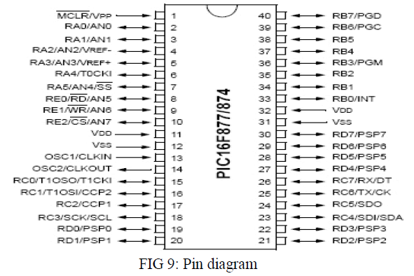 |
| The memory of a PIC 16F877 chip is divided into 3 sections. They are 1.Program memory, 2.Data memory and 3.Data EEPROM Program memory contains the programs that are written by the user. The program counter (PC) executes these stored commands one by one. Usually PIC16F877 devices have a 13 bit wide program counter that is capable of addressing 8K×14 bit program memory space. This memory is primarily used for storing the programs that are written (burned) to be used by the PIC. These devices also have 8K*14 bits of flash memory that can be electrically erasable /reprogrammed. Each time we write a new program to the controller, we must delete the old one at that time. Program counters (PC) is used to keep the track of the program execution by holding the address of the current instruction. The counter is automatically incremented to the next instruction during the current instruction execution.The PIC16F87XA family has an 8-level deep x 13-bit wide hardware stack. The stack space is not a part of either program or data space and the stack pointers are not readable or writable. In the PIC microcontrollers, this is a special block of RAM memory used only for this purpose. The data EEPROM and Flash program memory is readable and writable during normal operation (over the full VDD range). This memory is not directly mapped in the register file space. Instead, it is indirectly addressed through the Special Function Registers. The EEPROM data memory allows single-byte read and write. The Flash program memory allows single-word reads and four-word block writes. Program memory write operations automatically perform an erase-before write on blocks of four words. A byte write in data EEPROM memory automatically erases the location and writes the new data (erase-before-write). The write time is controlled by an on-chip timer. The write/erase voltages are generated by an on-chip charge pump, rated to operate over the voltage range of the device for byte or word operations. |
| MAX232: The MAX232 is an integrated circuit that converts signals from an RS-232 serial port to signals suitable for use in TTL compatible digital logic circuits. The MAX232 is a dual driver/receiver and typically converts the RX, TX, CTS and RTS signals. The drivers provide RS-232 voltage level outputs (approx. ± 7.5 V) from a single + 5 V supply via on-chip charge pumps and external capacitors. This makes it useful for implementing RS-232 in devices that otherwise do not need any voltages outside the 0 V to + 5 V range, as power supply design does not need to be made more complicated just for driving the RS-232 in this case. The receivers reduce RS-232 inputs (which may be as high as ± 25 V), to standard 5 V TTL levels. These receivers have a typical threshold of 1.3 V, and a typical hysteresis of 0.5 V. |
| The later MAX232A is backwards compatible with the original MAX232 but may operate at higher baud rates and can use smaller external capacitors – 0.1 μF in place of the 1.0 μF capacitors used with the original device. |
| It is helpful to understand what occurs to the voltage levels. When a MAX232 IC receives a TTL level to convert, it changes a TTL Logic 0 to between +3 and +15 V, and changes TTL Logic 1 to between -3 to -15 V, and vice versa for converting from RS232 to TTL. This can be confusing when you realize that the RS232 Data Transmission voltages at a certain logic state are opposite from the RS232 Control Line voltages at the same logic state. |
 |
SOFTWARE DISCRIPTION |
 |
 |
FUTURE SCOPE |
| The Entire circuit can be placed in a Watch or I-phone using Nano Sensor. |
| Reducing the work burden of doctors and the patients can be continuously monitored and measured. |
| Reduce the risk of death. |
| Hospitalization can be avoided. |
CONCLUSION |
| Some severe disease like heart failure, hypotension etc. requires continues monitoring. This project is initiated to alert the family members about patient’s health via SMS. Hope this will create an adverse change in the telemetry system and reduces life risk. Thus, doctors can monitor and diagnose the patient’s condition continuously and could suggest earlier precaution for the patients. This can reduce hospitalization of patients and never need for regular check-ups. Thus the project helps mankind to lead a healthy and safe life. |
References |
|