ISSN ONLINE(2320-9801) PRINT (2320-9798)
ISSN ONLINE(2320-9801) PRINT (2320-9798)
R.Jeevitha1, R. Prasad2, L.Nishanth3, D.Vignesh Kirubaharan4, S.M.Boobalakumaran5
|
| Related article at Pubmed, Scholar Google |
Visit for more related articles at International Journal of Innovative Research in Computer and Communication Engineering
Smart-puter is a mini computer designed for the two-wheelers to increase the level of security and control. This is designed with special algorithms such that it will be benefited by both user and the public servants. In this we have a complete digitalization of the vehicle components and make the display on the smart-puter. Smart-puter has the interfacing of displaying petrol and battery levels, lean position, turn indicator, engine temperature, global time, trip levels and the maximum speed set option. This also has a GPS module as well as it has the access to use GPS navigation and a GSM network so that he can always track the vehicle where it is through a particular cell number. This system design is done with the complete concentration over the power usage as well as the cost that plays the major role in the design technology. At the same it the GSM module is even programmed in such a way that if any breakdown of the vehicle occurs then its location where it has occurred is immediately sent as an SMS to the one registered number who always monitors the vehicle. It may be either due to accidents, climate and conditions. To make this task the special sectrol algorithms were designed.
Keywords |
| smart-puter, sectrol algorithms, GPS & GSM networks, power design |
INTRODUCTION |
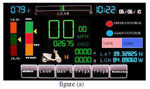
| Usage of hardware in every application is common but as per the latest trends, everybody started concentrating on the less hardware in a two-wheeler so that the fault detection is easy and the weight is reduced to balance it easily. These hardware meters once they are spoiled cannot be reused; hence, the option is change of the meters. Therefore, the use of plastic and metal is more concentrated on the manufacturing side, to avoid this we can simply use a smart computer in its place and make its complete work done by this computer. Therefore, the fault identification is easy. In this system, we can also change the tolerance when the wire property varies. This system is going to make the user directly change the tolerance property of the wire after a particular distance automatically. Since it varies, the software monitors it so that the output is unchanged. In simple meters, we can never get the accurate output but here we can get the accuracy by good formulation and sensor technology. The smart-puter screen works like the display panel of the speedometer and odometer mixed with many other display parameters. This is programmed in a particular manner such that it will give the display as in figure (a). All the individual parts made are connected via sensors and they are programmed and interfaced through the controller. |
| This system has an RTC interface to give the exact time and date as per the place and displays them on the screen. This has a GPS module in it so that the user can find the shortest path for his destination if he has less time to reach and it helps the user to track his position from the exact target and gives him the exact route to reach the destination. The GSM module embedded in this device helps us to track the vehicle whenever we lose it. The vehicle can be tracked with the help of an SMS service. The vehicle is registered to the network provider with some security norms. This system will help the user to track it only by the registered user from any place. |
| The Accelerometer is used in the system to find the lean of the vehicle and make the automated speed control with respect to the lean so that the accidents can be avoided, at the same time the rider can guide the pillion about his position. This helps the rider to be more comfortable for riding. The same sensor will also calculate the trip in the vehicle during sudden pits. |
| Flex touch temperature sensor is attached to the engine so that it monitors the engine temperature continuously and gives it to the system and displays on the screen as shown in figure (a). This system connected with many sensors and modules, needs power sharing from the battery, and at the same time, they need to consume less power from the battery so that the vehicle can use this device more efficiently. |
 |
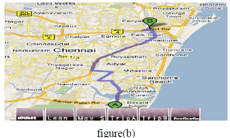
| This device does multi-control with the ARM 9 processor, and controls all the external elements those are interfaced to it without any delay and high accuracy. It seems to be to be simple but there are many front end and backend processes going simultaneously. The smart-puter is going to be programmed in such a way that it will work as a minicomputer with an arm processor in it. This will not only be useful for the user to identify the path but also to locate the map and check the remaining roots by which he can reach the destination from the point where he is now as in figure (b) below. |
 |
| The complete system having a water-resistant is placed in an appropriate place, where it can be protected from the rain and sunlight. This computer will control all the above-discussed modules in real time environment. This is completely programmed with the high precise time and task management so that the system is in synchronous with the vehicle. |
| The smart-puter has a temperature sensor, which is going to monitor the time-to-time change of the engine’s temperature so that if the engine is over heated then it immediately gives a blink of temperature display on the screen. This notifies the user about the status of the engine’s condition, which helps him in well maintenance of the engine. The RTC is used to make the complete system run in the real time environment so that the system works efficiently as well as the system will have a high-end control of the devices connected to the controller at the required time. |
| The fuel sensor will continuously monitor the level of the fuel in the tank and gives the information to the display. This will help the user in refilling the tank. The battery indicator will indicate the level of the battery and the state of charging and discharging. The odometer will continuously calculate the distance travelled and it is sent to the display. The GPS will continuously tell us the latitude and longitudinal position of the vehicle and the accelerometer will tell the inclination of the vehicle, which will help the user for safe drive. |
| The screen modes of this system will be functioning only with the control condition of the vehicle code so that the user will not get affected with any faults. So to avoid these things we have made this new design which can fulfill the necessary needs of the user. |
II. NEED FOR THIS DESIGN |
| Till this day we can find the sales for a two wheeler when compared to the cars as per the statics is always more and mostly every teen of age 19-28 will one a bike and its population is more that the elders. So as the sales of these vehicles are more when compared to the cars we have security systems in car to track them where as we don’t have anything for a two wheeler. And the thefts for a two wheeler were also more. Coming to the accidents many youngsters die due to two wheeler accidents and we come to know it very lately there is no system which informs us that the vehicle has meet with an accident so we need to wait till the morning to find him as a dead body. |
| Taking many of these real life scenarios we have seen all these into consideration by which the people are going to be safe of tracked as well as the vehicles. This will give some advantages like (1) the use of more amount of plastic and metal for these devices are reduced so cost is reduced for plastic as well as toxic during manufacture of plastic is also reduced. (2) The accuracy of the device is increased and made more precise so that the user finds more comfort. The mechanical loses are reduced. (3) The wear and tear at multi-places in the wire is reduced by using this device assembling in the vehicle where we directly detect the parameters from the vehicle points. (4) The security for the vehicle is increased and the track of vehicle is easy where ever it is, as the vehicle is linked with the cellular network. (5) The GPS navigation system will always guide the user about his destination path from where ever he is. (6) The system will have a speed limit indicator by which he will be restricted to the speed limit. (7) The trip and lean elements will help the user to save him from the accidents. |
III. DESIGN METHODOLOGY |
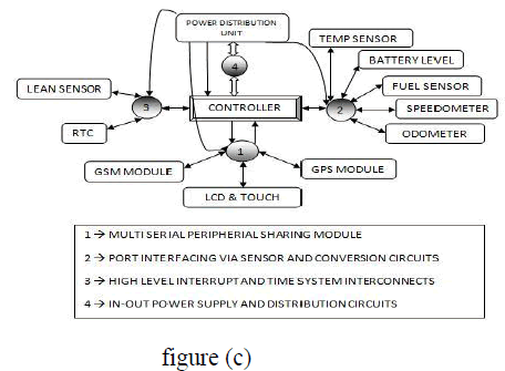
| This system development consists of both development of hardware and software modules for different interfacing modules and a real time code design is required to make the system work-fit. This system has different modules which need to get interfaced with the serial interfacing at different baud rates so that the system need to be connected to perform different tasks. As all the modules need to be performed parallel, we will be using a time-shared bank system. This system design in the block representation as shown below. |
| This shows the complete interconnection of the components to the controllers and the power distribution process. We need to go for this particular design because GPS, GSM and touch screen need to be connected with the serial hardware at a time with different baud rates such that GPS (9600 baud), GSM (4800 baud) and touch screen (19200 baud). Therefore, the process of processing the three devices parallel is one of the main aims of this design and development. The system is designed to satisfy this along with the power saving conditions as it needs to work with the battery. |
 |
IV. SECTROL ALGORITHM |
| For this system design I have developed a sectrol algorithm by which this complete element works with more efficiency and accurately. |
 |
A. VEHRITION-SECTROL ALGORITHM |
| In this algorithm we have clearly defined the working mode and the complete digitalization of the display unit. Here I am using a graphical LCD by on which I can set my display. The algorithm is as follows. |
i. Speedo & Odo-meter with mileage Design |
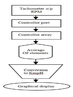
| In my system I have designed a special algorithm to give the speed (Kmph) from rpm (rotation per minute). This algorithm takes the data from the tachometer and it is converted to the speed and stored in a variable. Here we consider the different rpm readings for every 1 second and take the average value of these elements and convert that into the speed and displays and the variations were displayed beside it. We are going for this technique because all the meters in existence use, “analog rotation ïÃÆàdigital tachometer valueïÃÆàanalog display deviation parameter”. Even in the latest digital meters we are calculating the speed for each rpm data and make its averages for data collected for every second and display so the delay is more. So we made a new algorithm to calculate these parameters as shown in the flow design. |
ii. Fuel and lean sensing algorithm |
| In this we have used the fuel sensor inside the fuel tank but not of level detection it is a sensor which detects the concentration of the chemical element inside the tank with respect to the carbon-dioxide and gives us level depending on this concentration.It gives the values from 0.8 to 0.1 where if it is 0.8 implies that the tank is empty and 0.1implies that the tank if full. So depending upon the tank capacity we can set the reserve level .in this we have use a value as 0.65 as the reserve indication to the user. So it is not with respect to the tank size. |
| We have used an accelerometer in the vehicle placed exactly at the bottom of the seat of the rider so that it gives the tilt angle values at which the vehicle is so the person can adjust or can say the co-passenger to be seated properly or even if he is carrying a load at the back. At the same time the accelerometer is used to find the leans and it is displayed on the user screen at the same time if heavy vibrations occur it will record those to calculate the performance of the vehicle. |
iii. Engine breakdown control |
| Every vehicle which we have now will never indicate us the break-down situations and we feel it once it is done. So to avoid this breakdown of a tow-wheeler here we will be continuously monitoring the temperature of the engine with the help of a Flex touch temperature sensor. It gives the complete internal temperature of the engine and we even need to monitor the accelerator and oil. If there is an imbalance in these elements while in use then it leads to the breakdown so we monitor these elements and depending on the parameters it gives the indication on the engine temperature display in the blinking form in red color. For this to blink it is completely coded: So the parameter setting and programming and initializing these things will come into this particular category of sectrol algorithm. |
B. TRACK-SECTROL ALGORITHM |
| In this algorithm we will some across the complete flow of control and security for the GPS, GSM, and Vehicle tracking Technique.Here we have used a special techniques and designs for securing and tracking the vehicle from where ever we are about the condition of the vehicle. |
i. GPS track and sectrol design |
| In this system the GPS is used no as a simple tool of gathering the latitude and longitudinal data at the same time it is also set to use in a mode of auto destination set or by the manual tracking and displays the complete route map of the destination from source. This takes a particular logic and sequence and it is designed in this algorithm. |
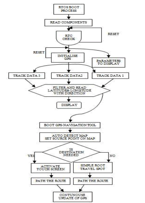 |
| This is the complete flow as well as the way how my algorithm works to make it track and update the elements at the same time detect the map and give it to the display. Also the destination concept is mentioned here. |
ii. GSM set-mode control algorithm |
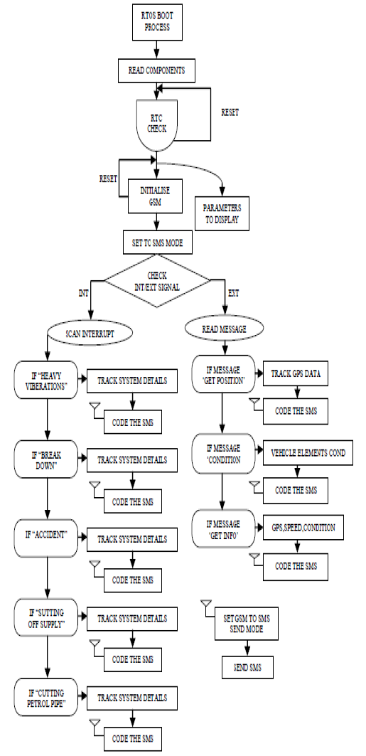
| This is the algorithm we have designed for use of the GSM in our design model in a particular manner. This algorithm consists of everything from the initialize of GSM to the complete control. It is made set mode parameterized in a way to be automatically set to the SMS read/write mode. Depends upon the type of interrupts via transiver or interrupts to the controller from different elements of the vehicle. |
| We have designed the system in a particular manner such that the user requests will be taken as the priority and decodes the user’s text and send him back the required details. When an internal problem occurs then the system will take them as the interrupts and send the required message depending on the type of problem occurred so the family members can know, this is a long flow which is shown in the flow diagram this flow will give the complete details about the working of the GSM and it coding and decoding functionality. This algorithm is completely designed by us in this vehicle giving the up-to-date conditions of the vehicle depending upon the requirements. This helped us a lot in giving vehicles to our loved ones’. |
 |
iii. GSM_RTO link design |
| Everyone knows that once we purchase a vehicle it has its RC BOOK which is called as registration certificate book which has a period of expiry depending upon the components used in the vehicle as well as the engine conditions. But 90 of every 100 will not renewal the RC book from RTO but use the vehicle on roads. |
| To avoid this we are giving the vehicle registered with a SIM registration validity 2 months extended from the vehicle RC expiry and loaded in the RTOS. A month before expiry the user will be continuously get the message on the display that the vehicle RC date is near, from the day of expiry it will send the SMS to the user as well as to the RTO office with vehicle no, it’s latitude and longitude positions, text message to the RTO. |
| They can use this and send the fine receipts to the users registered address. If the user neglects it after a months the complete system will shutdown. So he can’t start the vehicle. Once we pay the amount and made the vehicle check then the RTO will send the SMS to the vehicle registered number and it will be decoded and update the parameters in the RTOS about the RC expiry details. |
V. SOFTWARE DEVELOPEMENT |
| This system is designed with an RTOS to make it work fruitfully and accurately. The development of the RTOS is made with complete concentration of each and every step to be made and monitored and work as a real time machine with its exact decision capability. It is made to monitor all the elements embedded to it at the same time to accept the emergency signals and process it. Its priorities were changed at different scenarios depending on the requirement at that instant and the conditions at that instant. |
| This is designed with the complete parameter sets so that the monitoring of the system is easy and can be made feasible. This software for the system is developed in the layer designs that the bugs can be easily detected and recovered at the same time the process flow can be understood easily. We developed the RTOS with high accuracy and taken into consideration of the hard RTOS requirements and designed a higher prioritized Soft RTOS code to process it so that the system will not gets failure. |
VI. WORK TO BE DONE |
| This system is kept in the observation and the present results were fine but coming to the future we will take the step to guide the user using audio directions from the system so the user is not in a need to see the display. At the same time we can embed a support and a memory capacity in the system so that when a person needs to transfer some data from his friends he can directly use this system. And once he goes to his place he can place a USB device and gather the data from the vehicle and use it. |
| As this vehicle can transport data so there is no need to of a PC. During theft conditions, added to these features the system connects the GSM device with the speaker available in the vehicle when the owner makes up a call to the vehicle number so that the vehicle can be identified even if its number plate is removed. |
CONCLUSION |
| The smart-puter based sectrol for two-wheeler is the complete replacement of analog system to the smart computer where we use it as the multi functional screen to have the complete access of the pre existing speedometer and odometer in the present vehicles. |
| This new system will make the user to be happier about the security of the vehicle as well as about the easy control of the vehicle and increase the life span of the vehicle. This technology in vehicles will make the people to drive freely where ever they want without any fear and in short time with the help of the inbuilt navigation system as well as easy method of tracking is used in the system. |
| This system will completely make the user to opt it for the development to protect their life at the same time to increase the life span of the vehicle. Even the parents can sleep with peace even though the son has gone long drive on a bike. At the same time the driver safety is completely known when he is with the vehicle. |
References |
|