ISSN ONLINE(2278-8875) PRINT (2320-3765)
ISSN ONLINE(2278-8875) PRINT (2320-3765)
Anwarul Haque M.1, Dr. Rahul R. Dubey2
|
| Related article at Pubmed, Scholar Google |
Visit for more related articles at International Journal of Advanced Research in Electrical, Electronics and Instrumentation Engineering
There are many sources of energy that are renewable and considered to be environmentally friendly and harness natural processes. These sources of energy provide an alternate ‘cleaner’ source of energy, helping to negate the effects of certain forms of pollution. All of these power generation techniques can be described as renewable since they are not depleting any resource to create the energy. While there many large-scale renewable energy projects and production are in existence, renewable technologies are also suited to small off-grid applications, somewhere in rural and remote areas, where energy is often crucial in human development. Though the initial cost is high, central / state government should offer incentive programs to make “green” energy a more economically viable option. The main objectives are to bringing down the cost and component used in the power system through the enhancement of efficiency and reliability of the renewable energy sources with minimal maintenance & long life robust equipment to beat the future load-demand, to preserve the resources for last longing Universe for the sake of creature as well as to push India ahead from developing to developed country.
Keywords |
| solar cell, PV arrangements, System description, do’s and don’ts, PV characteristics, string inverter, sensors. |
INTRODUCTION |
| The present scenario of the Indian power sector is that the total installed capacity of Indian grid has 211765 MW. Out of this, 141715 MW is Thermal power, 39415 MW is Hydro power, and 4780 MW is Nuclear power & contribution of renewable energy sources are 25855 MW. Presently India is facing an energy deficit of 10% and a peak deficit of 15%. An average of 15 GW of power station installation is required annually till 2020 to chase the load-demand. The challenges that exist in India are |
| ïÃâ÷ Shortage of coal supply |
| ïÃâ÷ Erratic gas supply |
| ïÃâ÷ Land acquisition and environmental clearance |
| ïÃâ÷ Transmission losses (exceeding 30% in particular areas) |
| ïÃâ÷ Pitiable financial condition of distributor sector |
| ïÃâ÷ Global competition |
| To overcome the challenges faced by the power sector few measures have been taken place during last two decades. Transmission grid comprises 77500 km of 765 kV / 400 kV lines; 114600 km of 220 kV / 132 kV lines; 3 HVDC bipoles; 7 HVDC back to back and 6 TCSC with inter regional capacity of 14600 MW. Transmission voltages have risen from 440 kV (in 1977) to 765 kV (in 2000); from +600 kV HVDC to +800 kV HVDC (in 2011); ongoing plan is to rise to 1200 kV UHVAC. Earlier Generating unit size was less than 200MW and currently the unit sizes are ranging from 660MW to 1000MW. New transmission technologies which have emerged are |
| ïÃâç High voltage overhead transmission upto 1100 kV |
| ïÃâç Gas insulated cables / Transmission lines |
| ïÃâç HVDC light |
| ïÃâç Flexible AC Transmission system. |
| The developments in the generation sector are |
| ïÃâç Power former Engineering System |
| ïÃâç Distributed generations |
| ïÃâç Combined Cycle Power Plants. |
| Operational changes which are emerging include Wide Area Measurement System (WAMS) using Phasor Measurement Units and Power System Restructuring (Deregulation). |
| Study of power system is necessary so that we can analyse the fragile section of the system design and hub on that segment to achieve the target. If we focus on the off-grid solar power at the same time we are gaining on-grid power and able to provide that power to the needy one. Our need of study is to overcome the load-demand in the near future and at the same time to save the Global environment & resources. |
| Photovoltaic (PV) Solar power is harnessing the suns energy to produce electricity. One of the fastest growing energy sources are developing swiftly. Solar cells are becoming more efficient, transportable and even flexible, allowing for easy installation. PV has mainly been used for small and medium sized applications (calculator powered by a single solar cell to off-grid homes powered by a photovoltaic array). |
| Oil crisis in the year 1973 stimulated a rapid rise in the production of PV module. Since the leadership in the PV sector has shifted from US to Japan and Germany in the mid 1990s, Japan increased R&D funding, established net metering guidelines, and introduced a subsidy program to encourage the installation of residential PV systems (Copper Indium Selenide –CIS type). Solar installation in recent years have also largely begun to expand into residential areas, with government offering incentive programs to make “green” energy a more economically viable option |
A. Facility Overview is as under. |
| ïÃâç Modern state-of-the-art manufacturing automatic production line |
| ïÃâç Production capacity of 100 MW. |
| ïÃâç PV modules are manufactured by proven European technology |
| ïÃâç PV modules range from 3 to 300 watts. |
| ïÃâç Internationally recognized |
| ïÃâç High Reliability and Quality |
 |
 |
II. DESCRIPTION OF THE SYSTEM |
| It’s a case study project done by me on rooftop type 100-kW, SOLAR GRID POWER PLANT at Vaihwakarma Government Engineering College, Chandkheda, Gandhinagar, Gujarat (India). Green Energy Development Agency (GEDA) is the pioneer organisation in Gujarat state for such a revolutionary task, whereas Waaree Engineers Private Limited (Surat, Gujarat based) was formed in 2007 by the promoters of the WAAREE Group of Companies to begin its foray into Renewable Energy Sources. |
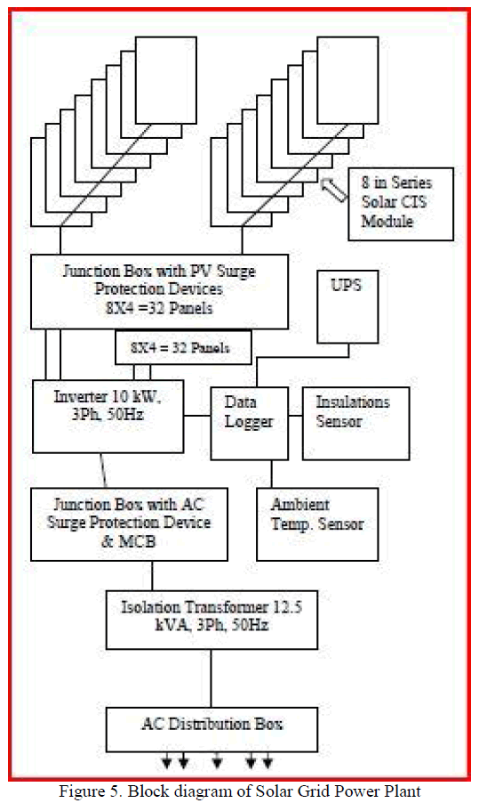 |
| This system is a multi-string inverter that converts direct electric current from a photovoltaic generator into alternating electric current and feeds it into the national grid. Photovoltaic panels transform energy from the sun into direct current (DC) electrical energy (through a photovoltaic field, also called photo voltaic (PV) generator; however, to feed the grid |
| it has to be transformed into alternating current (AC). This conversion, known as DC to AC inversion, is made efficiently without using rotating parts and only through static electronic devices (inverter). |
| When used in parallel with the grid, the alternating current generated by the inverter flows directly into the domestic electrical circuit, which is in turn connected, through a distributor, to the national grid. The solar energy system therefore powers all connected electrical devices, from lighting to household appliances, etc. |
| When the photovoltaic system is not supplying sufficient power, the power needed to ensure normal operation of the connected electrical devices is drawn from the national grid. If on the other hand excess power is produces, this is fed directly into the grid, so becoming available to other consumers. In accordance with local and national regulations, the power produces can be sold to the grid or credited toward the future consumption, so bringing down the cost. Block diagram of the system (Figure 5) is as above. |
III. DO’S AND DON’TS FOR SOLAR SYSTEM |
Do’s |
| ïÃÆü Ensure the solar PV modules are installed in the shade free sun in a proper direction. |
| ïÃÆü The PV module connections should be done in last. |
| ïÃÆü Ensure the tap/paper is removed from the battery cell vent plug before connecting the battery. |
| ïÃÆü The solar PV modules are to be cleaned regularly to remove the dust. |
| ïÃÆü In case red LED marked “LOW” glows, charge the battery is regularly charged so that is in full charged condition. |
| ïÃÆü Ensure that the battery is fully topped up with distilled water. The electrolyte level conditions in the battery must be checked in 30 days and if the electrolyte level has gone down, it is to be topped up with distilled water. Ensure that the battery plates are always covered with electrolyte (Wherever Battery is applicable). |
| ïÃÆü Petroleum jelly (not grease) should be applied on the battery terminals to avoid corrosion of the terminals. |
Don’ts |
| X Do not use grease for applying to battery terminals (wherever applicable). |
| X Do not use acid for topping up the battery (wherever applicable). |
| X Do not clean the solar PV modules with acid/chemicals/detergent etc. |
| X Don’t temper with settings of Controller or the Solar Inverter. |
| X In case of any problem contact the source from where one has procured the system. |
IV.PV PANEL CHARACHERISTICS |
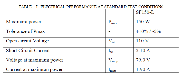
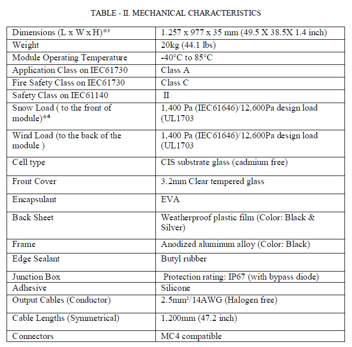
| From the Product Data Sheet SF150-L 150W module here summarizes few characteristic performances as bellows. |
 |
 |
V. 3-PHASE STRING INVERTER |
| The three phase string inverters in the 8-20 kW power classes are suitable for interior and exterior installations; from the 8kW rooftop system to the megawatt park. Their low weight and volume ensure simple handling and saved space during the installation. This is simplified further by a plug & play functionally together with an interface and Ethernet. |
| Even at a low eradiation, the inverters achieve a peak efficiency of up to 98.2%. This is ensured by an excellent MPPtracking and a wide input voltage range of up to 380-850 V. Through the very low levels of loss over the complete input voltage range, it can be configured for convection cooling only. With the integrated data logger it is possible to monitor this system around the clock. These data can be transferred via the standard cable or an optional wireless connection via radio module. |
VI. IRRADIANCE SENSOR AND INTEGRATED MODULE TEMPERATURE SENSOR |
| The sensors record variances between the possible and the actual power production levels and deliver key indicators relating to the quality of the system as a whole. Solar Log (one type of Data system) continuously compares the yield data from the solar data power plant with the measurement results from the various sensors. If a variance exists, the Solar-Log generates an error message. The most important element in the Sensor Box is the irradiance sensor. This delivers a reference value for solar radiation and enables conclusions to be drawn about possible power generation. Even at low levels of solarization, power dips can be identified reliably and error messages can be generated. Due to the installed internal module temperature sensor, a power “dip” is easier to analyze. Communication benefits between the Solar-Log and the Sensor Boxes are (1) Solar-Log generates an error message in response to any variance that occurs (2) Errors and malfunctions can be filtered out and analyzed rapidly and reliably (3) The sensor evaluation provides information about the cause of the fault (4) Up to 9 Sensor Boxes can be connected to the Solar-Log. |
| The irradiance sensor is equipped with a high-quality mono crystalline cell, which is rugged and specifically designed for long-term use in outdoor locations. The sensors are installed directly to the solar power plant connected to the Solar-Log via interface. |
| Our objectives are to bringing down the cost and component used in the power system through the enhancement of efficiency and reliability of the renewable energy sources with minimal maintenance & long life robust equipment to beat the future load-demand, to preserve the resources for last longing Universe for the sake of creature as well as to push India ahead from developing to developed country. |
OBSERVATION |
| Standard Test Condition (STC) for electrical performances is: 1000 W/m2 Irradiance, module temperature 25ºC and a spectral distribution of irradiance according to air mass 1.5. Isc and Voc are + 10% tolerance of the rated values at STC. Sorting range for Pmax is within + 2.5W of the rated value at STC. |
| From typical I-V characteristics at STC (Figure 6) it is observed that Efficiency reduction of maximum power from an irradiance of 1000 W/m2 to 200W/m2 at 25ºC is typically 3.0%. The standard deviation for the reduction of efficiency is 2.6%. Typical I-V Characteristics of a Solar cell is also shown in Figure 7. |
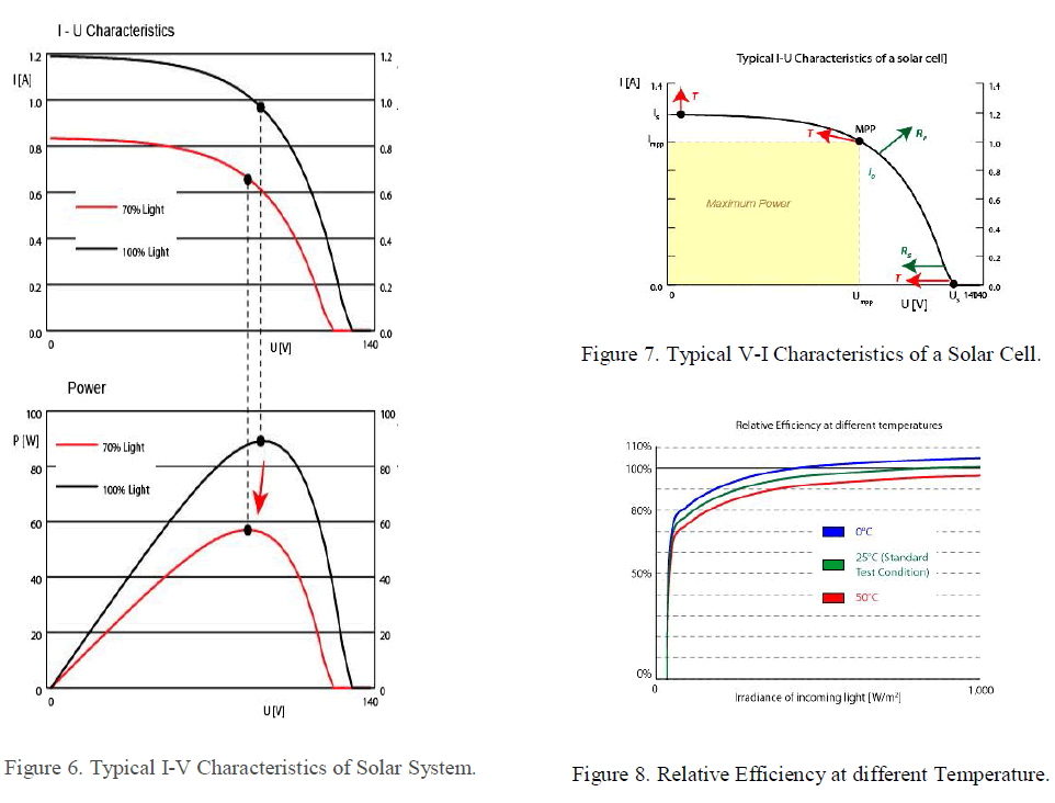 |
| From thermal characteristics it is observed that there is minor change in current with temperature variation but incredible voltage level increases with temperature. Relative Efficiency at different temperatures is as shown in the Figure 8. |
| Here 3 to 5 % variation in efficiency observed from morning to evening is implausible. With regular / periodic cleaning of PV panels a significant increase in rated output as well as in percentage efficiency is observed with respect to time. |
VIII. FUTURE SCOPE |
| The ongoing development of interconnection standards and regulations will present both market opportunities and technology challenges for the power sector. Further trends and development efforts will need of focus on improving efficiency and reliability, communication and interface, reduce parts and points of failure, packaging and bringing down the cost. |
IX. CONCLUSION |
| Indeed, global study of renewable energy sources is necessary so that one can analyse the fragile section of the system design and hub on that segment to achieve the target. If we focus on the off-grid solar power at the same time we are gaining on-grid power and able to provide that power to the needy one. Only the drawback is it requires huge area for installation and initial cost is high. There is neither fuel nor labour charges have to born to harness the Power. Therefore, Central Government or State Government should offer incentive programs to make “green” energy a more economically viable option. |
References |
|