ISSN ONLINE(2278-8875) PRINT (2320-3765)
ISSN ONLINE(2278-8875) PRINT (2320-3765)
Dr.B Mahesh Kumar1, R Babu Ashok2
|
| Related article at Pubmed, Scholar Google |
Visit for more related articles at International Journal of Advanced Research in Electrical, Electronics and Instrumentation Engineering
This paper presents set of harnessing solar energy for electrical vehicle where BLDC machine is a sole heart of Electric Vehicle (EV). The solar Photo Voltaic (PV) array is modeled for study purpose. Requirement of huge voltage gain is fulfilled by a non-galvanic modified Single Ended Primary Inductor Converter (SEPIC). The conventional 3 phase H-bridge inverter (Voltage source Inverter (VSI) - SPWM drive based) is used in BLDC motor. Basic modeling of BLDC machine with few assumptions is used for entire experimentation to validate the analytical study. MATLAB based simulation is carried for a 2 HP BLDC machine system. The performances like Speed, Torque, Current, Voltage and Back emf of the system are analyzed , validated and resulting waveforms are confirming to battery equivalent system performances is given.
Keywords |
| Solar PV, modified SEPIC, VSC, H-bridge BLDC, SPWM, EV |
INTRODUCTION |
| As fossil fuels are getting exhausted and more over the electric power generation is highly polluting the atmosphere, the entire world focus on renewable energy sources in which harnessing of solar power using PV module is taken as the first step in this paper. Solar power is abundant in tropical countries like India. Moreover the solar panel is portable so its usage is unlimited and more suitable for some drugs (maintained at low level temperatures) has to be transported for long distances. The DC voltage gain of the PV modules can be increased by SEPIC converter but the gain is limited. To increase the voltage gain abruptly modified SEPIC converter with non-galvanic isolation is chosen in this paper. The increased DC voltage is inverted to AC by means of control logic circuits conventional. The stator armature windings of (BLDC) Brushless DC Motor makes easy to dissipate heat away from the windings. BLDC Motor finds wide range of applications from hard disk drives to hybrid electric vehicles owing to the following advantages over brushed DC motors viz., |
| a) Higher speed ranges and efficiency. |
| b) Higher dynamic response & Power density |
| c) Better speed Vs. Torque characteristics |
| d) Noiseless with 4 quadrant operation and maintenance free. |
| e) Tenacious & low electromagnetic pollution |
| f) Regenerative braking. |
| It is otherwise known as (ECM) electronically commutated motor and having trapezoidal back emf waveforms and are fed with rectangular stator currents. To reduce the cost without compromising the performance is a tough task. Cost and circuit complexity are the important factors for design tradeoffs between technology and design hardware. The combined analysis of energy, environmental issues with respect to driver is a paradigm shift. Since the rotor has no winding they are not subjected to centrifugal forces. The rotor position is sensed by two methods |
| a) Hall sensor - temperature sensitive, reduce system reliability but suitable for low cost, low speed & low resolution. |
| b) Back emf- promising device widely used because reliable. |
| Every commutation sequence has one of the windings energized positive, the second negative and the third left open. The hall sensor signal changes the state when the voltage polarity of back emf crosses from a positive to negative or from negative to positive. In ideal cases this happens on zero crossing of back emf but practically there will be a delay due to winding characteristics. Another important aspect is at very low speed the back emf is very low amplitude to detect zero crossing. The motor has to be started in open loop from standstill and when sufficient back emf is built to detect the zero crossing point, the control should be shifted to the back emf sensing. The minimum speed at which back emf can be sensed is calculated from the back emf constant of the motor. |
MODELLING OF PV ARRAY |
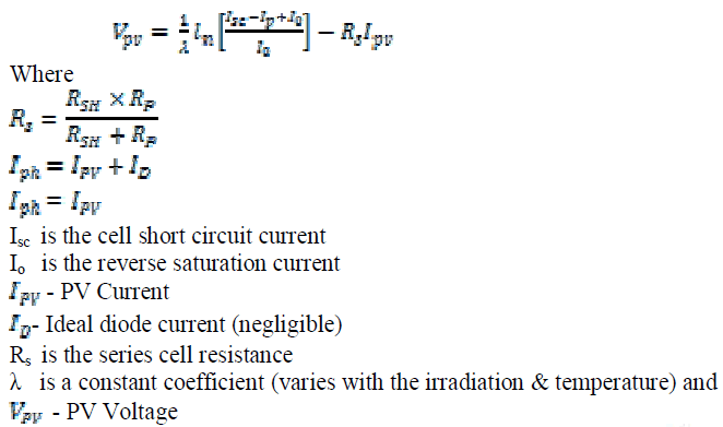
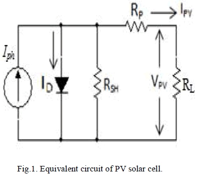
| The equivalent circuit of SPV is shown in Fig. 1. The output P-V characteristics of cells are nonlinear as shown in Fig. 2. The solar PV output voltage is |
 |
 |
| To enhance more PV power (Ns) numbers of PV modules are connected in series and (Np) numbers of PV strings are connected in parallel in the PV array. The current rating and voltage rating of a PV array depends on 2 factors viz., irradiation and temperature levels. Equation (1) is calculated for different irradiation levels (G=600, 800, 1000 W/ ) for the constant temperature, T=250C from the Ppv-Vpv characteristics of Fig. 2 as shown. |
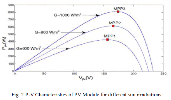 |
| From the above Fig. 2 P-V characteristics of PV module for different sun irradiations only one operating point is located on every Ppv-Vpv characteristics for which maximum PV solar power can be harnessed. This specific operating point for PV array is known as Maximum Power Point Tracking (MPPT) and identified by MPPT controller. For modeling of PV array the generalized equation of photovoltaic cell voltage is taken is to account and the output characteristics are also studied. |
MODELLING OF BLDC MOTOR |
| For the simplified analysis and simulation purpose few assumptions are made in BLDC motor. The Assumption are |
| 1. Three phase windings are symmetrical i.e., balanced system. |
| 2. Magnetic saturation is neglected. |
| 3. Hysteresis and eddy current losses are not considered. |
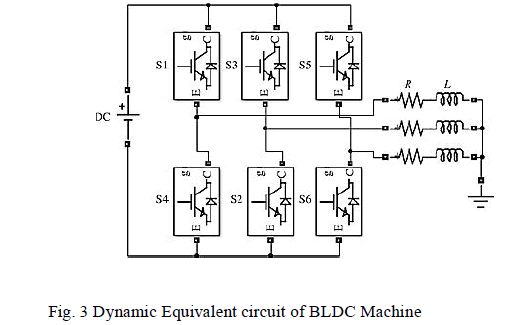
| 4. Inherent resistances of each motor winding are R and self-inductances are L and they are considered as constant. |
| 5. Stator winding are wye- connected hence zero sequence quantities are absent. |
| The Dynamic equivalent circuit of BLDC machine is shown in Fig. 3. |
 |
| BLDC motor is fed by a 3 phase voltage source. The source can be either sinusoidal or square wave, with the condition that the supply voltage should be less than the maximum voltage limit of the motor. The supply voltage pertaining to each phase of the winding can be written as |
 |
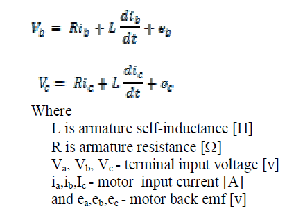 |
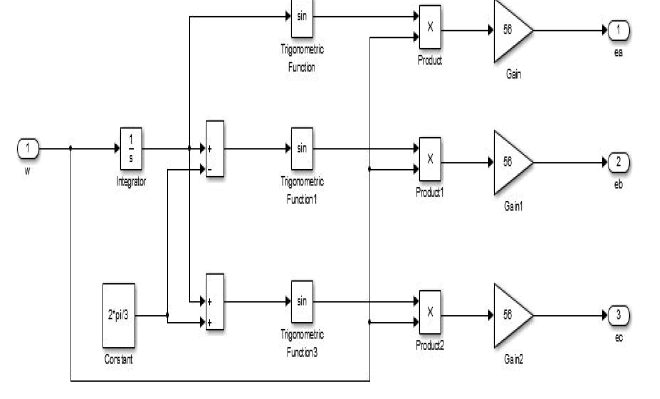
| Where the back emf is function of rotor position with 1200 phase angle difference hence |
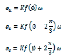 |
| where |
| k is back emf constant of one phase |
| Ø - electrical rotor angle[ 0el] |
| - rotor speed [rad/s] |
| f - supply frequency |
| The relation between electrical rotor angle and mechanical rotor angle Øm (rad) is |
 |
| where |
| P – Number of rotor poles. |
| The total electrical torque ‘Te’[Nm] developed at the output can be expressed as follows |
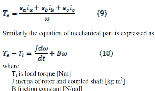 |
| Hence for BLDC machine simulation and analysis purpose the above seen phase voltage, back emf and Torque equations are utilized. |
MODELLING OF MODIFIED SEPIC |
| SEPIC stands for ‘Single Ended Primary Inductance Converter’ in which the output DC voltage gain is more than conventional DC converters. To improve the voltage still higher, modified SEPIC converter is incorporated because losses and noise are reduced. |
A. SEPIC Converter: |
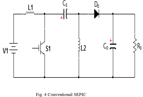
| The circuit of SEPIC converter is shown in Fig.4. Its significant is nothing but switching voltage is equal to the sum of the input and output voltages. |
 |
B. Modified SEPIC Converter |
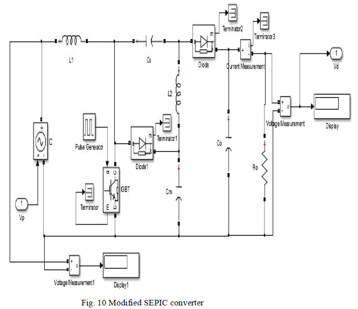
| The modification of the SEPIC converter is accomplished by adding two components, diode DM and the capacitor CM from SEPIC converter as shown in Fig. 5. |
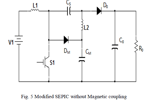 |
| To improve the converter static gains some modifications are proposed. The capacitor cm is charged with the output voltage the polarity of the capacitor cs is reversed. The assumption made is capacitors are considered as a voltage source and the semiconductors are considered to be ideal. In the continuous conduction mode (CCM) it operates in 2 modes. |
| 1) Mode-I [t0 – t1]: |
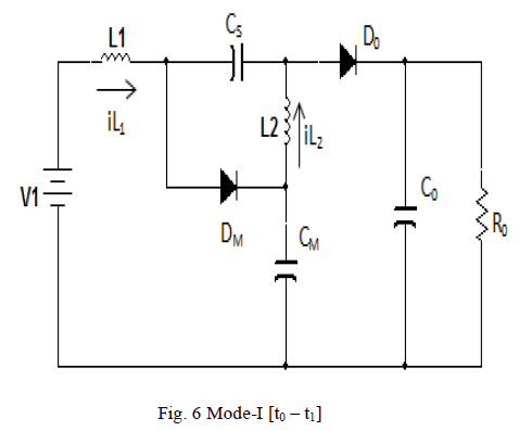 |
| The equivalent circuit of mode-I is shown in Fig. 6. Where switch S is turned off at to and the energy stored in the input inductor L1 is transferred to the output through the capacitor Csand output diode D0 and further transferred to the capacitor Cm through the diode Dm. Hence switch voltage is equal to Cm capacitor voltage. The energy stored is the inductor L2 is transferred to the output through the diode D2. |
| 2) Mode-II [t1-t2]: |
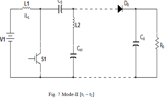 |
| The equivalent circuit of mode-II is shown in Fig. 7. Where switch S is turned on and the diodes Dm and D0 are blocked at the instant t1 and the inductors L1 and L2 store energy simultaneously. The input voltage is applied to the input inductor L1 and the output voltage Vcs -Vcm is applied to the inductor L2. The Vcm voltage is higher than the Vcs voltage. The maximum voltage in all diodes and in the power switch is equal to Cm Capacitor voltage. The output is equal to the sum of the voltage across capacitors Cs and Cm. The average L1 inductor current is equal to the input current and the average L2 inductor current is equal to the output current. |
| In CCM operation the static gain of the convertor at the steady state is |
 |
| This gain (11) is higher than conventional converters. The maximum switch voltage is equal to the Vcm voltage (12) but switch voltage is lower than converter output voltage. |
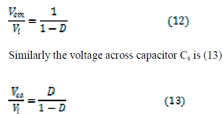 |
| Where D is duty cycle. |
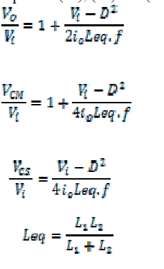
| The static gain and capacitor voltages ( operating in DCM (discontinuous mode) are represented in equation (14), (15) and (16) respectively. |
 |
C. Design aspect of the modified SEPIC converter |
| The converter is operating in CCM with the following details |
| Output power, Po =1500W |
| Input voltage, Vi =45V |
| Output voltage, Vo =450 V |
| Switching frequency, f =24 khz |
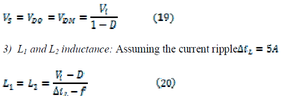
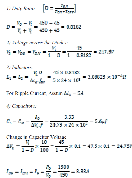
| 1) Switch duty cycle: With reference to static gain the duty cycle is |
 |
| 2) Switch and diode voltages:The diode output voltage |
 |
 |
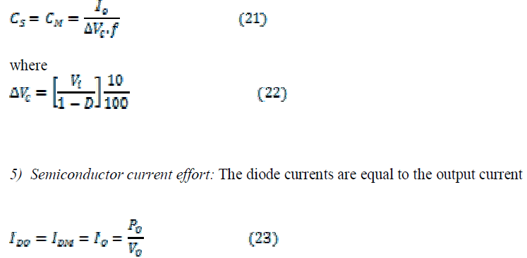
| 4) Capacitor Cs and Cm: Let the capacitor voltage ripple âÃâóVc = 10% of the nominal voltage of Cm |
 |
SIMULATION |
A) Solar PV Model |
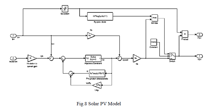
| The solar PV Model is created using the foreseen equation (1) |
 |
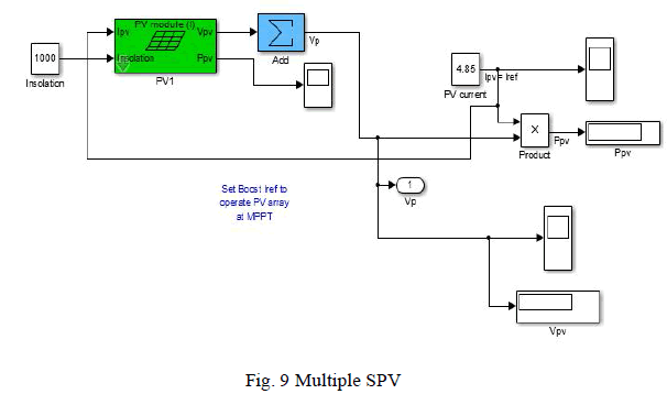
B) Multiple SPV |
| To increase the voltage rating in a PV array ‘ns’ number of modules can be connected in series and to increase current rating ‘np’ number of PV modules can be connected in parallel. In this paper parallel connection is preferred because voltage gain is taken care by SEPIC converter |
 |
C) Modified SEPIC Converter |
| The modified SEPIC converter is designed as per the Reference paper [2] and as shown in Fig.5. The component values are desired by the equations (11-23) |
 |
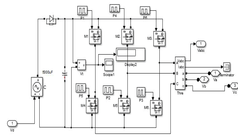
D) Inverter |
| The inverter used in this paper is conventional (VSI) voltage source inverter driven by simple sine PWM technique. |
 |
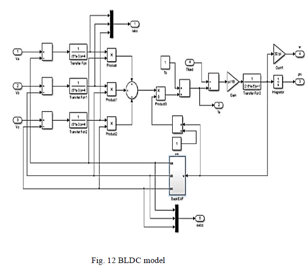
E) BLDC model |
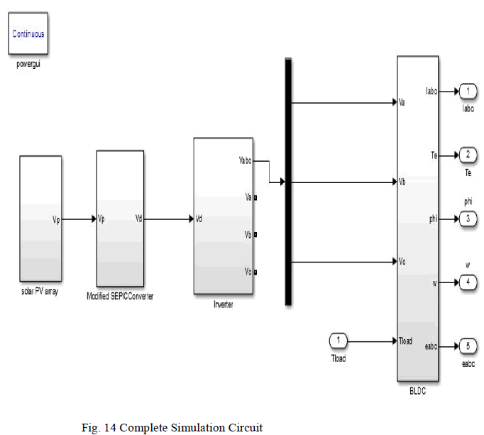
| The supply voltage in Phase ‘a’ (Va) vide equation (2), Phase ‘b’ (Vb) vide equation (3), Phase ‘c’ (Vc) vide equation (4), Electromagnetic Torque vide equation (9) and Motor Torque vide equation (10) are used in the proposed BLDC motor model. |
 |
F) Back EMF |
| The sine back emf of Phase ‘a’ (ea) vide equation (5) , Phase ‘b’ (eb) vide equation (6) and Phase ‘c’ (ec) vide equation (7) are obtained from the back emf Simulink model |
 |
| G) Complete Simulation Circuit |
 |
RESULT ANALYSIS AND DISCUSSION |
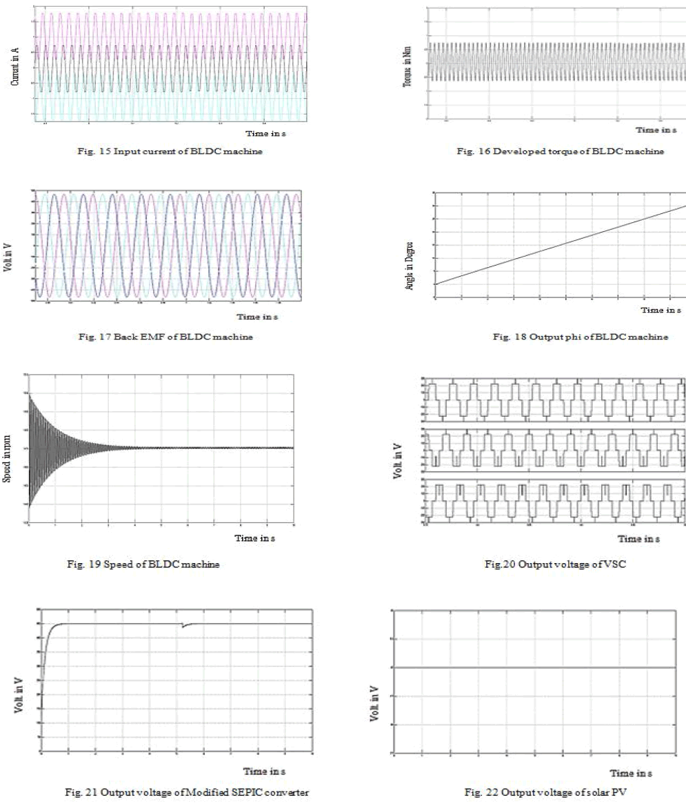
| The figure shows the result for the following BLDC Drive Parameters with constant speed and Torque. |
A. Solar Photovoltaic Array |
| Each solar cell produces 24V, 1.65A, two serially connected solar cell produced 48V,3.3A and 10 Parallely connected combination produce 48V, 33.3A |
B. Modified SEPIC Converter |
| Output power Po= 1500W, Input Voltage Vi = 45V, Output Voltage Vo=450V and the frequency is 24Khz. |
 |
C. Three Phase Full H-Bridge (VSI) |
| DC input voltage is 450V, AC Output Voltage 415V, IO =2.3187A |
D. BLDC machine |
| AC input Voltage =415V, Input current = 2.318A, Output Power= 1.5 KW |
WAVEFORMS |
 |
CONCLUSION |
| The modelling presented in this paper for solar PV array and BLDC machine with sinusoidal back emf are much useful to carry research further in solar electric vehicle, open loop modified SEPIC converter fed, VSC implemented BLDC drive is designed and experimented in MATLAB platform to validate analytical results. To carry such a research a 2Hp BLDC machine is chosen as a test machine for that [ten (10) parallel (two PV cell connected in series)] Twenty PV cell with 24V and 1.65A is used as energy source. The 45V solar voltage is boosted to 450V DC by modified SEPIC converter, 450V DC is supplied to VSI fed BLDC machine. The performance curves are closely equivalent to that of the battery supplied Electric vehicle. In near future suitable control technique will be employed to the system for improving the performances and hardware implementation is also an another scope. |
References |
|