ISSN ONLINE(2278-8875) PRINT (2320-3765)
ISSN ONLINE(2278-8875) PRINT (2320-3765)
Dr.T.Vamsee Kiran1, M.Prasanthi2
|
| Related article at Pubmed, Scholar Google |
Visit for more related articles at International Journal of Advanced Research in Electrical, Electronics and Instrumentation Engineering
This paper presents a new direct torque control (DTC) strategy for BLDC motor based on speed behaviour of PI and SMC based DTC of BLDC motor. In conventional direct torque controlled BLDC motor drive, there is usually undesired torque and flux ripple. So tuning PI parameters(Kp, Ki) are essential to DTC system to improve the performance of the system. PI controller is widely used in motor control system due to the simple control structure. In conventional PI controller, the performance of the motor may cause unexpected torque disturbances. To overcome the problems with PI controllers, in this paper, sliding mode controller is proposed to resolve the speed tracking problem for DTC of BLDC motor drive. The simulation results of DTC of BLDC motor drive with PI & SMC controllers are compared in the MATLAB/simulink environment.
Keywords |
| PI and SMC controllers,BLDC motor, DTC, MATLAB/simulink. |
INTRODUCTION |
| BLDC motors have many advantages over brushed DC motors and induction motors. A few of those have better speed versus torque characteristics, high dynamic response, high efficiency, long operating life, noiseless operation. The permanent magnet brushless dc motor is gaining popularity because of its usage in computers, aerospace, military and robots. The BLDC motor is inherently electronically controlled and requires rotor position informationfor proper communications of the current. The only drawback of conventional dc motors is that they need a commutator and brushes which are subjected to wear& tear and require regular maintenance. In BLDC motors the functions of brushes and commutator were implemented by position sensor and inverter. There are several methods to vary the speed of the BLDC motor over a wide range. The most modern technique is direct torque control method (DTC).The DTC offers many advantages like fast torque response, no need of coordinate transformation and less dependence on the rotor parameters. The conventional PI (Proportional, Integral) control method is widely used in motor control system due to the simple control structure and easiness of design. However tuning the parameters of PI controller is a difficult task. In conventional PI controller, the performance of the motor may cause unexpected torque disturbances. In order to resolves the speed tracking problem for DTC of BLDC motor drive various approaches have been suggested such as sliding mode controller (SMC) and Fuzzy controller, ANFIS controllers etc |
| The proposed sliding mode controller(SMC) is one of the modern controller used to solve speed tracking problemsfor DTC of BLDC motor drive.This controller works irrespective of the parameter variations and load torque disturbances. The SMC method is an excellent control technique and a promising approach for solving the conventional PI controller parameters problem. |
Purpose of the present work: |
| The objective of the present work is to provide an alternative approach to solve speed tracking problems for DTC of BLDC motor drive.This method uses the principle of Direct Torque Control, which is based both on field oriented control (FOC) as well as on the direct self-control theory. DTC offers direct control of stator flux and electrical torque there by reducing the speed error resulting in better speed control of BLDC drive. In this paper one of the modern controllerscalled sliding mode controller (SMC) is used to reduce the speed error of BLDC motor, hence overcoming the major drawbacks of conventional PI controller. |
MATHEMATICAL MODELING OF BLDC MOTOR |
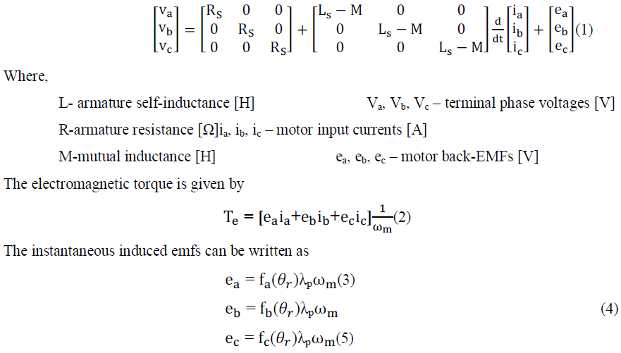
| The BLDC motor has been modeled by using the following equations |
| The coupled circuit equations of the stator windings in terms of motor electrical constants are |
 |
 |
BLDC DRIVE OPERATION WITH INVERTER |
| The power circuit topology of a three-phase VSI fed BLDC motor is shown in Fig.1. S1 to S6 are the six power switches.The IGBT is gated at regular interval of 600 in proper sequence so that a 3-phase AC is synthesized at o/p. |
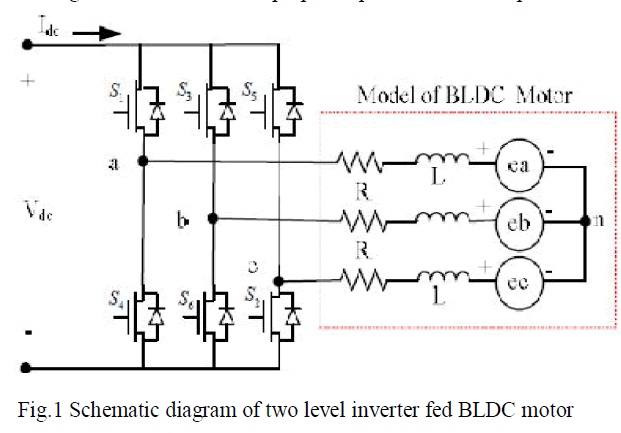 |
| The machine is represented in the figure by a three-phase equivalent circuit, where each phase consists of stator resistance R, equivalent self-inductance L and a trapezoidal EMF in series. The inverter acts like an electronic commutator that receives switching logical pulses from the absolute position sensor. The speed and electromagnetic torque of BLDC motor is controlled by the selection of optimal inverter switching modes. |
DIRECT TORQUE CONTROL STRATEGY |
| DTC strategies have been widely implemented in induction machine drives. They allow a direct control of the electromagnetic torque and the stator flux through the application of suitable combinations of the control signals of the inverter switches. Therefore in DTC, Torque is controlled through the selection of optimal inverter switching states. DTC technique is superior to vector control because of the advantages like fast torque response, low inverter switching frequency, low harmonic loss, absence of coordinate transformation. This control strategy in this paper has been applied for BLDC drive. Block diagram of direct torque control of BLDC motor is shown in Fig.2. |
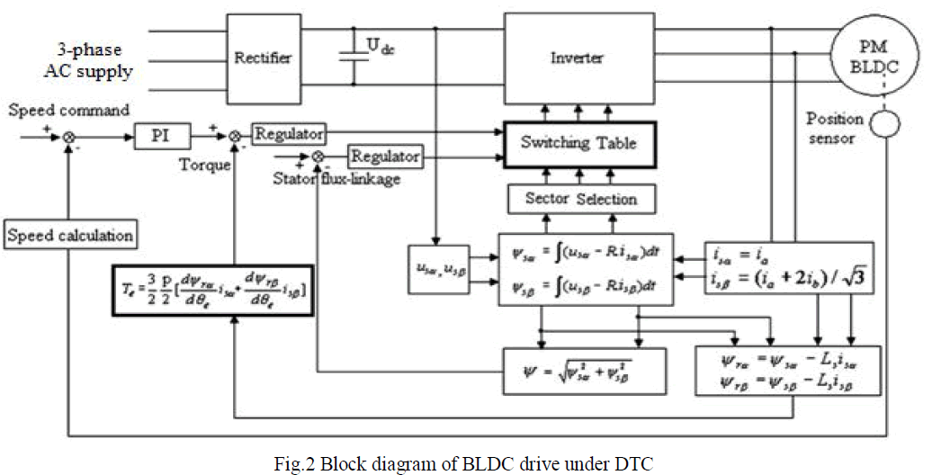 |
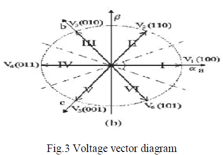
| The basic control algorithm of DTC is consists of two independent hysteresis comparators producing the error signal of stator flux and torque.A two-level hysteresis flux comparator and a three level hysteresis torque comparator compare the actual values to the reference values produced by flux and torque reference controllers. Depending on the outputs from the two hysteresis controllers, the optimum switching logic selects one of the six voltage vectors and two zero voltage vectors generated by a VSI in order to keep stator flux and torque within the limits of two hysteresis bands.The angle of the stator flux vector is used to determine the voltage sector as shown on the Fig3. |
 |
| The conventional PI control method is widely used in motor control system due to the simple control structure and easiness of design.In PI controller, the speed of the motor is compared with its reference value and the speed error is processed in PI controller. The output of this controller is considered as the reference torque. However the PI controller cannot result in perfect control of the drive as the parameters Kp, Ki are not properly tuned. The undesired torque and flux ripple may occur in conventional direct torque controlled BLDC motor drive. |
| In this paper, to overcome the drawbacks of PI controller, a sliding mode controlleris proposed to resolve the speed tracking problem in BLDC motor drive. |
PROPOSED SLIDING MODE CONTROLLER |
| A sliding mode controller (SMC) is an adaptivecontroller that results in robust performance of thedrive even under the parameter variationconditions and load torque disturbances.SMC can be employed in BLDC motors, induction motors, synchronous motor drives for applications such as robot drives and machine tool control etc. In Fig.2, the PI controller is replaced by the SMC. |
| The SMC has been modeled by using the following equations: |
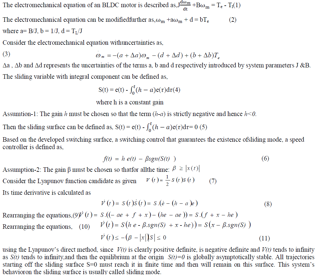 |
| When the sliding mode occurs on the sliding surface, then, S(t)= dS(t) = 0 and the tracking error e(t) converges to zero exponentially. |
| The reference torque command Te *by using sliding mode controller (SMC) can be obtained as, |
 |
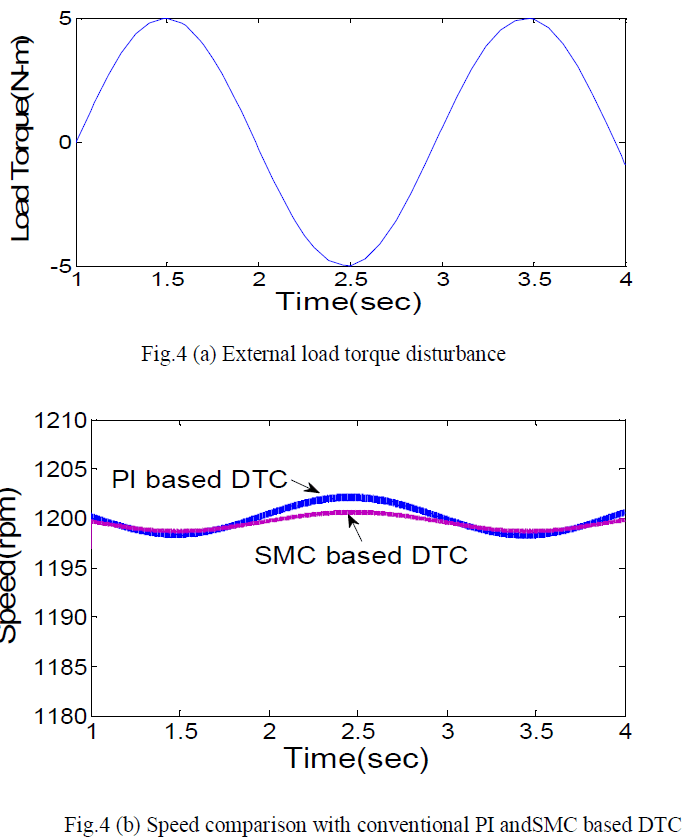 |
| In the fig 4(b), it shows the plot of time Vs speed for a load disturbance applied to DTC of BLDC drive in fig.4 (a), by comparing the speed behaviour of conventional PI based DTC with SMC based DTC of BLDC motor, there is less ripple in speed and results in better speed performance of the SMC based DTC. |
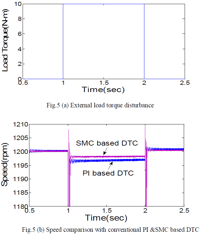 |
| In the fig 5(b), it shows the plot of time Vs speed for a load disturbance applied to DTC of BLDC drive in fig.5 (a), by comparing the speed behaviour of conventional PI based DTC with SMC based DTC of BLDC motor, there is less ripple in speed and results in better speed performance of the SMC based DTC. |
 |
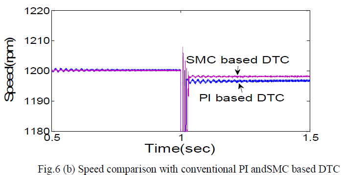 |
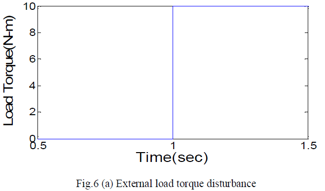
| In the fig 6(b), it shows the plot of time Vs speed for a load disturbance applied to DTC of BLDC drive in fig.6 (a), by comparing the speed behaviour of conventional PI based DTC with SMC based DTC of BLDC motor, there is less ripple in speed and results in better speed performance of the SMC based DTC. |
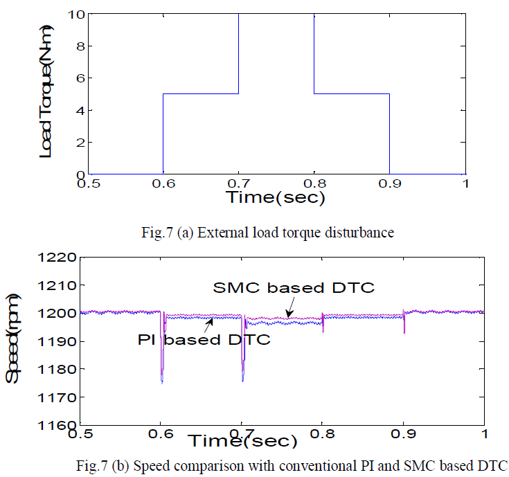 |
| In the fig 7(b), it shows the plot of time Vs speed for a load disturbance applied to DTC of BLDC drive in fig.7 (a), by comparing the speed behaviour of conventional PI based DTC with SMC based DTC of BLDC motor, there is less ripple in speed and results in better speed performance of the SMC based DTC. |
| It has been observed that the speed performance of SMC based DTC of BLDC motoris better when compared with the conventional PI controller based drive. |
CONCLUSIONS |
| In this paper the proposed SMC controller scheme has been implemented and applied to the DTC of BLDC drive.The proposed SMC method has effectively minimized the speed error. This proposed method has finally improved the speed performance of the BLDC motor when compared with that of a conventional PI controller based DTC of BLDC motor. It can be concluded from the simulation results of SMC based DTC of BLDC motor drive that the controller has improved the speed performance of the BLDC motor irrespective of the load torque fluctuations. |
References |
|