ISSN ONLINE(2278-8875) PRINT (2320-3765)
ISSN ONLINE(2278-8875) PRINT (2320-3765)
R.G.Rajesh1, C.Balaji2
|
| Related article at Pubmed, Scholar Google |
Visit for more related articles at International Journal of Advanced Research in Electrical, Electronics and Instrumentation Engineering
This paper presents an efficient simulation model of PID controlled brushless direct current motor drive using MATLAB / SIMULINK is presented. The Brushless direct current (BLDC) motor is efficiently controlled by PID controller. The Mathematical modelling BLDC motor is verified. The dynamic characteristics of BLDC motor (speed and torque) and as well as current and voltages of the inverter components are easily observed and analysed by using developed model.
Keywords |
| BLDC, Speed Control, PID, MATLAB / SIMULINK. |
INTRODUCTION |
| Brushless DC motors have been used in various industrial and domestic applications. Due to overweighing merits of this motor ,there is continuing trend to propose improved control schemes to enhance the performance of the motor[1- 2].Torque smoothness is essential for high performance motion control applications and obtaining an accurate and ripple free instantaneous torque is of great important for BLDC motor[3-4].The Brushless DC motor is driven by trapezoidal voltage strokes coupled with the given rotor position .The voltage strokes must be properly aligned between the phases ,so that the angle between the stator flux and the rotor flux is kept close to 120Ãâ¹ÃÅ¡to get the maximum torque[5-6]. |
II.LITERATURE REVIEW |
| Sun-kwon lee-This paper presents the stator and rotor shape designs in interior permanent magnet (IPM) type brushless dc motor for reducing torque fluctuation. The partly enlarged air-gap made by rotor unequal out diameter and stator core structure with pole shoe modification is introduced. The torque ripple reduction is achieved by upgrading torque value at minimum torque position and their detail characteristics are compared. The final stator and rotor shape of IPM type BLDC motor is decided by design of experiments (DOE) process. The magnetic field and torque characteristics are analyzed by dimensional (2D) finite element analysis (FEA) and their performances are validated by experimental results. |
| Nikola milivo jevic-Brushless dc (BLDC) drives have received significant attention, owing to their high efficiency, electromagnetic interference, and high mechanical reliability due to the absence of brushes in commercial, residential, and industrial applications. In generating mode, they are very suitable for small wind and hydro generator applications, as well as integrated starter alternators in hybrid electric vehicles. This paper discusses digital pulse width modulation control for a BLDC drive in both motoring and generating modes of operation. This control strategy is simple and robust, requires no current sensors, and is not computationally intensive. Owing to these attributes, the technique can be implemented on a low-cost field-programmable gate array. This paper investigates potential stability issues due to the simplicity of this control under various conditions of load disturbances and also owing to the reduction in processor capability. Lyapunov stability criteria have been used to analyze the closed-loop stability of the system. Furthermore, an approximate discrete model has been developed, and the stability of the system is analyzed to ensure closed-loop operation under various sets of loads, speeds, and input voltages. |
| C. Sheebajoice- Brushless DC (BLDC) motor drives are becoming more popular in industrial, traction applications. This makes the control of BLDC motor in all the four quadrants very vital. This paper deals with the digital control of three phase BLDC motor. The motor is controlled in all the four quadrants without any loss of power; in fact energy is conserved during the regenerative period. The digital controller dsPIC30F4011, which is very advantageous over other controllers, as it combines the calculation capability of Digital Signal Processor and controlling capability of PIC microcontroller, to achieve precise control. |
III.MATHEMATICAL MODEL OF BLDC MOTOR |
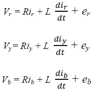
| Modelling of a BLDC motor can be developed in a similar manner as a preface synchronous machine. Since there is a permanent magnet mounted on the rotor, some dynamic characteristics are different. Flux linkage from the rotor depends upon the magnet material. Therefore saturation of magnetic flux linkage is typical for this kind of motors. As any typical three phase motors, one structure of BLDC motor is fed by a three phase voltage source the source is not necessarily to be sinusoidal. Square wave or other wave shape can be applied as long as the peak voltage does not exceed the maximum voltage limit of the motor. Similarly, the model of the armature winding of the BLDC motor is expressed as follows. |
 |
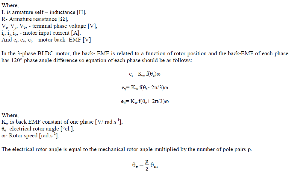 |
| θm – Mechanical rotor angle [rad]. |
| Total torque output can be represented as summation of that of each phase. Next equation represents the total torque output: |
 |
IV.PID CONTROLLER |
| The ‘CONTROLLER_MOD’ block has three sub blocks. Each of these blocks is a finite state machine. Each of the machine has the task of maintaining the required current either in R, Y or B phase windings. |
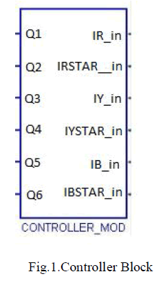 |
| After the reference have been generated by the estimate block, the ‘CONTROLLER_MOD’ block takes over and triggers the appropriate gates of the inverter to establish and maintain the desired current. For reference the structure of the inverter is as shown |
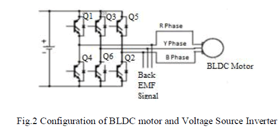 |
| The logic used by any of the machines is very simple ,for example ,for the machine that controls the U phase ,it checks to see whether the actual current in phase R(IR) is greater than the required current(IRSTAR),if it is then it will activate transistor Q4.otherwise ,it will activate transistor Q1. |
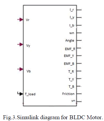
| BLDC MOTOR: The core of the state space model calculates the five variables given by equation .these variables are further processed to give a total of 25 outputs that can be monitored. The Block takes the voltage values that are impressed upon the windings along with the load torque information .The values to be input are derived from the general Simulink sources and not the sim power systems block set. The outputs are calculated by solving differential equations so only numerical values are required. We had tried to use sim power system block set, but that approach requires very powerful processors and very large memory. The time required to compute values was in the order of hours, so there is definitely a trade-off here, but I have tried my best not to compromise on the accuracy |
 |
V.SIMULINK MODEL OF THE BLDC MOTOR |
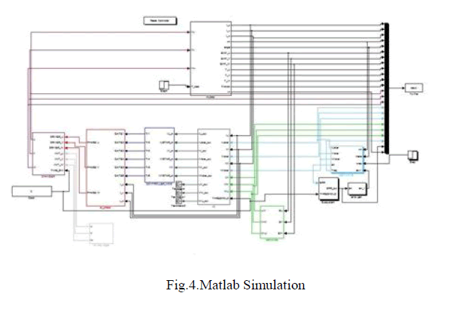
| Fig .4 shows the BLDC motor SIMULINK model. The model was developed in the rotor reference frame of the BLDC motor. BLDC motor control system consists of many parts BLDC motor noumenon,inverter,controller. |
 |
VI. RESULT AND DISCUSSION |
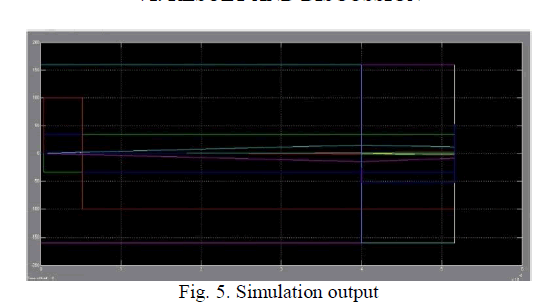 |
| We do the simulation experiments according to the simulation model established of BLDCM control system .The parameters are used in this case: rated voltage 24V, the rated speed is 8000rpm, the pole number is 4. |
VII.CONCLUSION |
| In this paper ,a complete analysis of brushless DC drive system has been performed by using PID controller .The simulation model which is implemented in a modular manner under MATLAB/Simulink environment allows that many dynamic characteristics such as voltage ,rotor speed, phase current and mechanical torque can be effectively considered. Furthermore, sensor less control is the only choice for some applications and a high performance is required. |
References |
|