ISSN ONLINE(2278-8875) PRINT (2320-3765)
ISSN ONLINE(2278-8875) PRINT (2320-3765)
Bandi Naga Surendra1, Murali Dasari2, T.Ravi kumar 3
|
| Related article at Pubmed, Scholar Google |
Visit for more related articles at International Journal of Advanced Research in Electrical, Electronics and Instrumentation Engineering
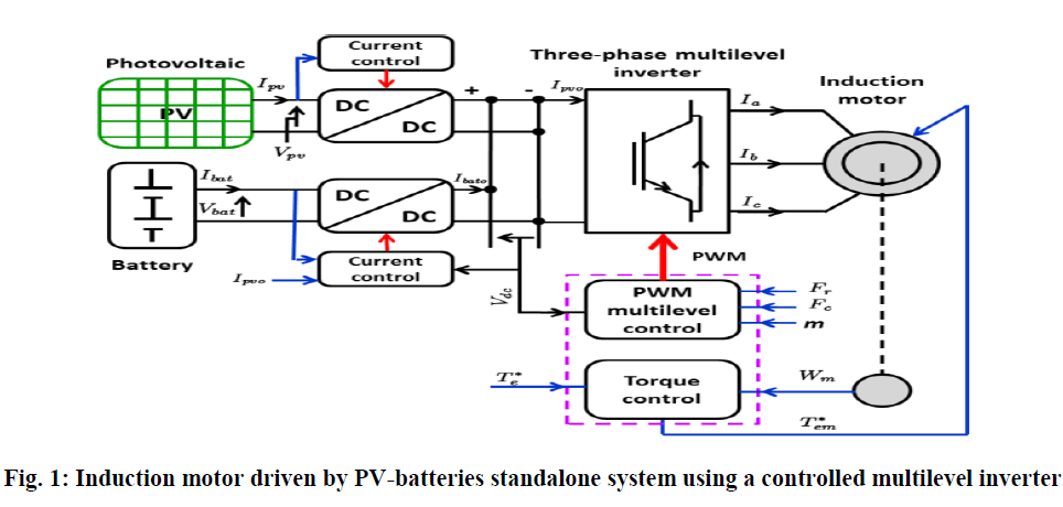
This paper deals the control of a multilevel inverter fed with an Induction motor supplied by a Photovoltaic (PV) panel and a batteries bank. With the increase in number of levels the power quality of multilevel inverter signal may depends. However, in this paper solve the problem of how many number of levels necessary to increase for harmonic reduction. The harmonics content of the output signals are analyzed by comparing the different levels of diode-clamped multilevel inverter is shown. A sinusoidal Pulse Width Modulation (SPWM) method for a multilevel inverter that supplied an induction motor is developed. The controller equations are such that the SPWM pulses are generated automatically for any number of levels. The effectiveness of the propose method is evaluated in simulation. Matlab/Simulink is used to implement the control algorithm and simulate the system.
Keywords |
| Induction motor, Multilevel inverter, Multilevel SPWM, THD |
INTRODUCTION |
| Numerous industrial applications have begun to require higher power apparatus in recent years. Some medium voltage motor drives and utility applications require medium voltage and megawatt power level. For a medium voltage grid, it is troublesome to connect only one power semiconductor switch directly. As a result, a multilevel power converter structure has been introduced as an alternative in high power and medium voltage situations. A multilevel converter not only achieves high power ratings, but also enables the use of renewable energy sources. Renewable energy sources such as photovoltaic, wind, and fuel cells can be easily interfaced to a multilevel converter system for a high power application. |
| The concept of multilevel converters has been introduced since 1975[1].The term multilevel began with the three-level converter. Subsequently, several multilevel converter topologies have been developed. However, the elementary concept of a multilevel converter to achieve higher power is to use a series of power semiconductor switches with several lower voltage dc sources to perform the power conversion by synthesizing a staircase voltage waveform. Capacitors, batteries, and renewable energy voltage sources can be used as the multiple dc voltage sources. |
| The commutation of the power switches aggregate these multiple dc sources in order to achieve high voltage at the output; however, the rated voltage of the power semiconductor switches depends only upon the rating of the dc voltage sources to which they are connected. Among the control algorithms proposed in the literature in this field [3-4-5], the SPWM, appears most promising. It offers great flexibility in optimizing the design and it is well suited for digital implementation. It also helps to maximize the available power. |
| The main advantage of multilevel inverters is that the output voltage can be generated with a low harmonics. Thus it is admitted that the harmonics decrease proportionately to the inverter level. For these reasons, the multilevel inverters are preferred for high power applications [6-7]. However, there is no shortage of disadvantages. Their control is much more complex and the techniques are still not widely used in industry [8-9]. In this paper, modelling and simulation of a multilevel inverter using Neutral-Point-Clamped (NPC) inverters have been performed with motor load using Simulink / MATLAB program. In the first section multilevel inverter control strategies are presented before to detail a study of nine-level inverter in the second section. Total Harmonic Distortion (THD) is discussed in the third section. |
| The aim is to highlight the limit at which the multilevel inverters are no longer effective in reducing output voltage harmonics. |
II. MULTILEVEL INVERTER CONTROL STRATEGIES |
 |
A. The three-level inverter control strategy: |
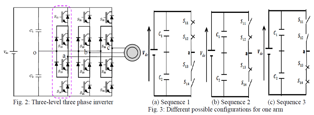
| three-phase three-level inverter is shown in fig (2). The circuit consists of three arms. Each arm has four switches. Every switch is connected in anti-parallel with a diode. Here it describes the operation of three possible combinations for each one leg as shown in fig (3). The voltage Vao between the phase "a" and the neutral point O is defined entirely by the switches position (0 „openâÃâ¬ÃŸ or 1âÃâ¬ÃŸclosedâÃâ¬ÃŸ). Switch sets [S11, S12], and [S13, S14] have complementary positions. When [ S11, S13] are open [S12, S14] are closed. The three-level NPC inverter is mostly used for medium-voltage highpower applications [11].In this converter, the number of commutation sequences (Seq) is equal to 24= 16., where 4 stands for the number of switches per arm and 2 is the number of state per switch (0, 1).Vdc is the DC-bus voltage. Only three commutation sequences are possible. They are represented at Table 1. |
| Fig. 3 shows the configurations of the inverterâÃâ¬ÃŸs arm which correspond to the three possible commutation sequences: |
| - Sequence 1: S11, S12conduct and S13, S14 open (Fig.3.a). Vao= +Vdc/2. |
| - Sequence 2: S11, S13 conduct and S12, S14 open (Fig.3.b). Vao = 0. |
| - Sequence 3: S13,S14 conduct and S11,S12 open (Fig.3.c). Vao = − Vdc /2. |
| Sequences 1, 2 and 3 are applied in this order periodically. |
 |
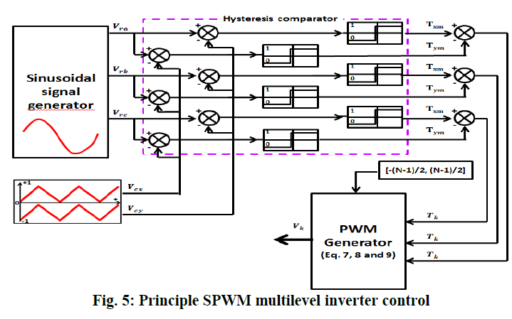
| A pulse width modulation is used to control the switches Consider Fig. 4 and Fig. 5, the reference voltage Vra compared to the positive and negative sawtooth carrier Vcx and Vcy respectively. The comparator output is sent to the switches (Insulated Gate Bipolar Transistor or IGBT) to generate the machine phase voltage. |
| The modulated SPWM voltage has the following characteristics: |
| - SPWM pulses frequency is the same as the sawtooth carrier fc. The magnitude is 1 (f SPWM = fc,) |
| - the fundamental frequency is controlled by fr which is the same as the reference voltage Vra frequency. |
 |
| The inverter output voltages are written as follow |
 |
B. The higher level inverter control strategy |
 |
| The last study for the three-level voltage inverter is now extended to higher level inverters. For an n-level inverter, it is possible to determine the number of components that are needed per arm (number of switches, diodes, carrier, etc). |
| Numbers of inverter components calculation : |
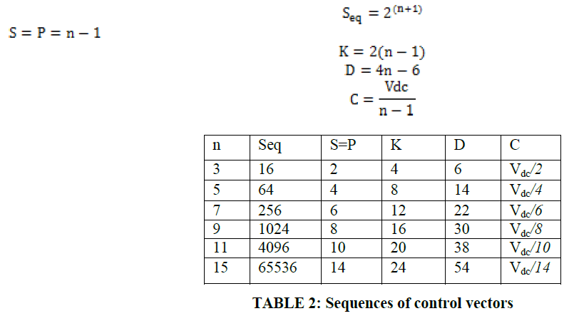
| Define Seq as the number of commutation sequence possibilities. S is the number of secondary voltage sources. K stands for the number of switches per phase. D is the number of diodes loop including the diode switches per phase. C represents the magnitude of the voltage across each capacitor and P is the number of carriers. |
| The following equations provide how these quantities are calculated and table 2 shows the values for several multilevel inverters. |
 |
Calculation of carrier : |
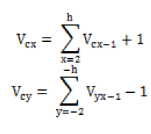
| A bipolar sawtooth carrier is illustrated at Figure 6. The voltages Vcx and Vcy,_ have the expression given by equation as fallows: |
 |
| Calculation of reference voltages : |
| The balanced three-phase reference voltage is given by : |
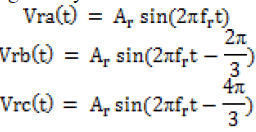 |
| where Vr is the three phase reference voltage. |
Calculation of the comparator : |
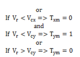
| The comparator uses the reference and carrier signals to generate a binary signal according to the following equation : |
 |
Calculation of the adder : |
| The parameter Tk is the difference between Txm and Tym . It is therefore calculated as follows. |
 |
Calculation of inverter control vectors: |
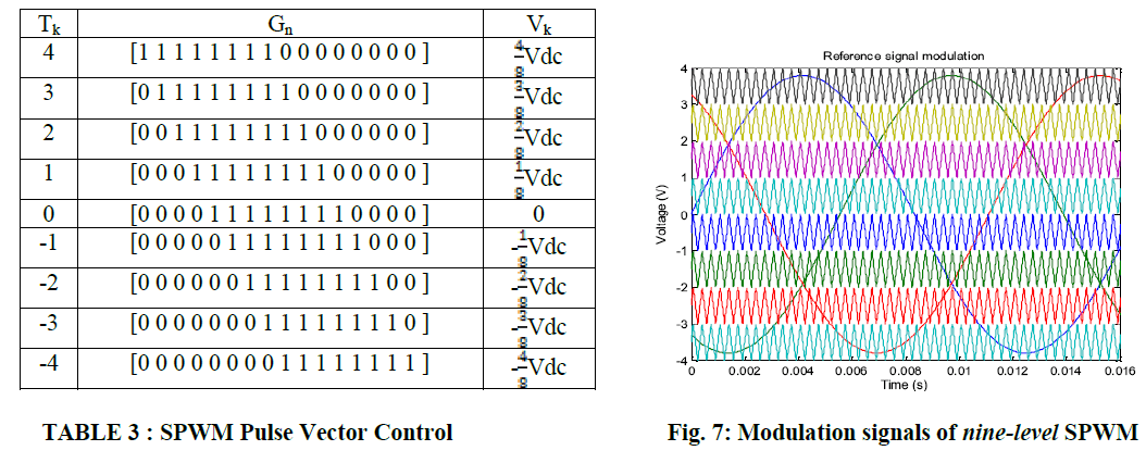
| The generation of the pulse vector that control the inverter is very important. The pulse vector can be generated by applying the Gn vector for each Tk according equation. The inverter output voltage Vk is given by equation as fallows : |
 |
III. CASE STUDY: NINE-LEVEL INVERTER INDUCTION MACHINE CONTROL |
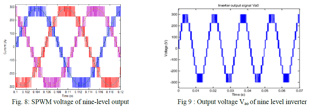
| This section presents on a case study for a nine-level inverter that is used to drive an induction machine. From equation (4), when (n = 9), the number of components required is: 8 secondary voltage sources, 16 switches per arm, 30 diodes per arm, and 8 carriers. The corresponding SPWM control pulse vectors are given at Table 3. Fig. 7 shows the reference and carrier signals. The voltages across the capacitors have the same values Vdc/6. The inverter output voltage Vk which is the voltage between phase and neutral is given at Table 3. The three phase voltages Vao,Vbo and Vco have the same shape but they are phase-shifted by 120°. |
 |
| One can notice that SPWM voltage of the nine level output is shown in fig (8).In fig (9) shows the output voltage waveform has nine-level . |
 |
IV. TOTAL HARMONIC DISTORTION (THD) ANALYSIS OF MULTILEVEL INVERTER |
| The main criterion for assessing the quality of the voltage delivered by an inverter is the Total Harmonic Distortion (THD). This section will be devoted to analyzing the inverters performance according to their number level. Level three, nine and fifteen inverters will be considered. The main aim is to see if the low order harmonics amplitude will decrease when the number of level increases. The inverter is usually followed by a low pass filter since higher frequency harmonics are easy to filter. This means that the performance of multilevel inverters can be improved by cancelling or reducing lower order harmonics. Lower order harmonics generate the most important currents when an inductive load is used. |
| The THD is a measure of closeness in a shape between the output voltage waveform and its fundamental component. It is defined as the ratio of the RMS value of its total harmonic component of the output voltage and the RMS value of the fundamental component. Mathematically, THD as follows: |
 |
V. SIMULATION CIRCUIT & RESULTS |
 |
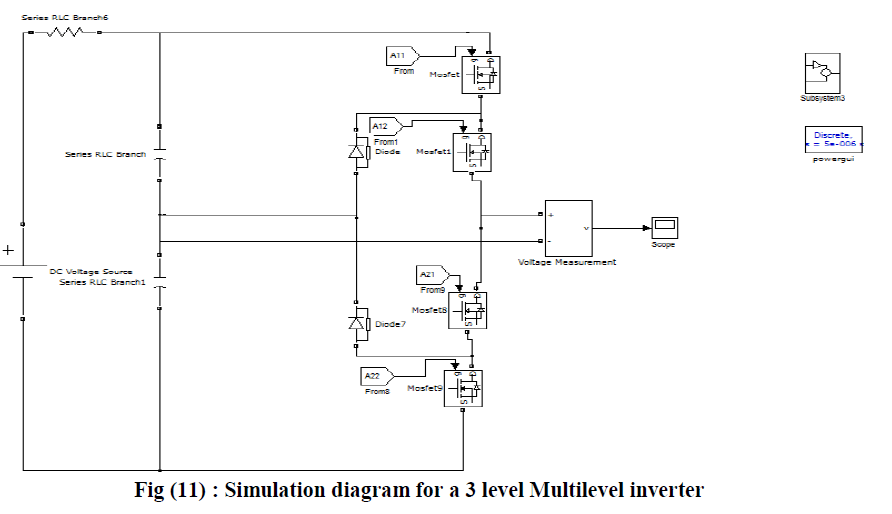 |
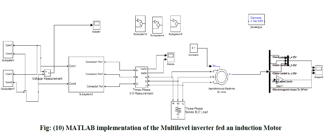
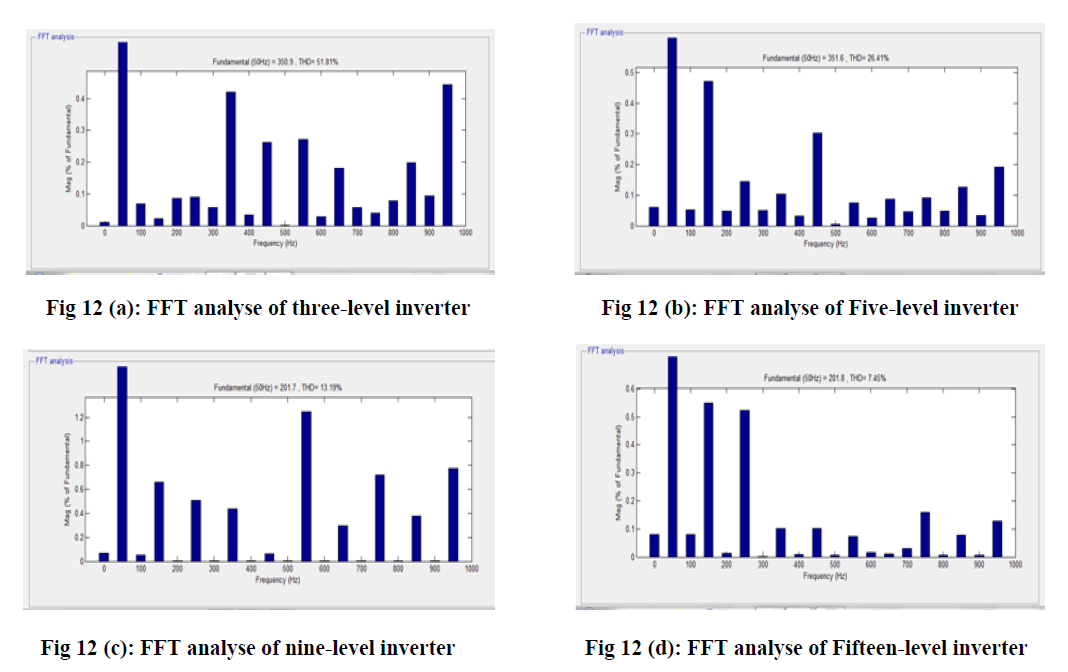
| In Fig 10 indicates that the MATLAB circuit implementation of the Multi level inverter fed an induction Motor. Fig 11 represents the Simulation diagram foe a 3 Level multilevel inverter. By using with different multilevel inverters i.e., 3,5,9 and 15 level the THD values are found form FFT analysis. Here different Multilevel inverters FFT analysis are shown in below figures. |
 |
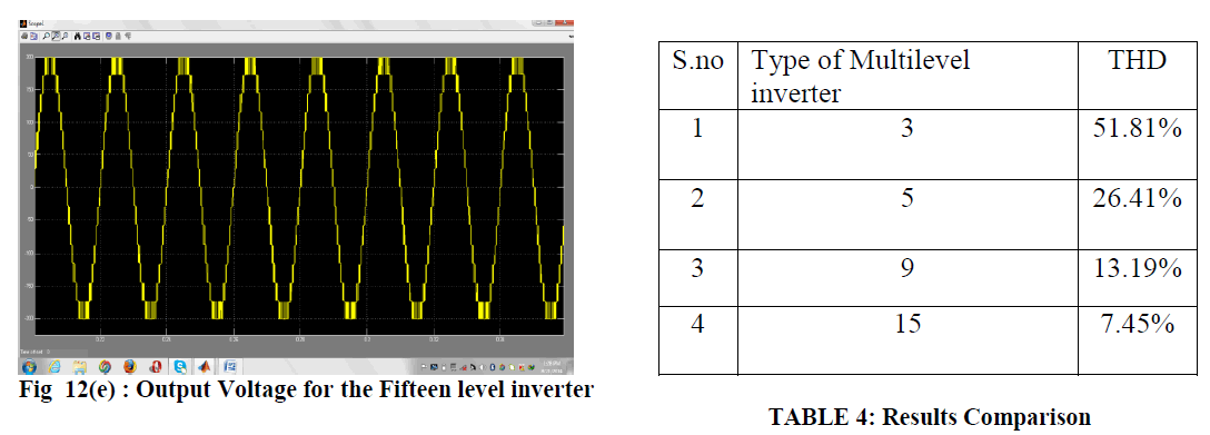 |
| In Fig 12 (a),(b),(c) & (d) are the FFT analysis for the 3,5,9 &15 level multilevel inverters. The Output voltage of the fifteen level multi level inverter. Finally the results Comparison table will gives the various THD values for different levels of multilevel inverter is shown in TABLE 4 . This simulation demonstrates that the magnitude of the harmonics get smaller when the number of level is increased. It becomes therefore easy to remove those harmonics with a simple low-pass filter. |
V. CONCLUSIONS |
| In this paper, a general multilevel SPWM control algorithm for n-level inverter has been modelled and simulated using Matlab/Simulink. This algorithm can generate automatically SPWM pulses for any level of inverter by changing only a parameter n which is the number of inverter level. Simulation of 3,5,9 and fifteen level inverter connected to induction motor has been performed and the generated signals THD are analysed. The system is supplied by a PV panel and batteries bank. That gives energy autonomy to the system. Simulation results give a better quality of stator current in terms of low harmonics, thus reducing the adverse effects on of the machine life and eventually the electrical network which supplies it. We have also highlighted that at fifteen-level, the harmonics are very low. These latter can be easily eliminated with a simple low-pass filter. So it is not necessary to continue increasing the inverter level. |
References |
|