International Journal of Advanced Research in Electrical, Electronics and Instrumentation Engineering
ISSN ONLINE(2278-8875) PRINT (2320-3765)
ISSN ONLINE(2278-8875) PRINT (2320-3765)
Parul Taneja 1, Lakhwinder 2
|
| Related article at Pubmed, Scholar Google |
Visit for more related articles at International Journal of Advanced Research in Electrical, Electronics and Instrumentation Engineering
In this paper, the effect of STATCOM for improving the stability of the multi machine power system is investigated. The STATCOM is used to control power flow of power system by injecting appropriate reactive power during dynamic state. Simulation results show that STATCOM not only considerably improves transient stability but also compensates the reactive power in steady state. Therefore STATCOM can increase reliability and capability of AC transmission system. To illustrate the performance of the FACTS controller (STATCOM), a three machine nine bus, Multi- Machine Power System has been considered.
Keywords |
| MATLAB; Simulink; STATCOM; |
INTRODUCTION |
| Electrical power lines are used to distribute electricity from power plants to the end consumers. The process is broken down into two main parts, transmission and distribution. The electrical power is generated at the generating station as per the requirement it can be stepped up and power is transmitted through transmission lines. That electrical power is then stepped down and carried through distribution lines and delivered to consumers. |
| power system is an interconnected network with components converting mechanical energy continuously into electrical form and transporting the electrical energy from generating sources to loads. Most if not all of the world’s electric power supply systems are widely interconnected, which involves various connections inside utilities of their own territories which extend to inter utility interconnections and then to inter-regional and international connections. |
| Electric power systems mainly have three separate components namely: |
| 1) Generation |
| 2) Transmission |
| 3) Distribution. |
| Electric power is generated at the power generating stations by synchronous alternators that are usually driven either by steam or hydro turbines. Almost the power generation takes place at generating stations that may contain more than one such turbine-alternator combinations known as turbo-alternators. Depending upon the type of fuel used, the generating stations are classified as thermal, hydro, nuclear etc. Many of these stations are located from load centre away. Hence the electric power generated at any of these stations has to be transmitted over a long distance to the load centers that are usually situated in cities and towns. This process is called power transmission. |
II. POWER SYSTEM STABILITY |
| Power system stability concept is defined as that property of a power system that enables it to remain in a state of operating equilibrium under normal operating conditions and to regain an acceptable state of equilibrium after being subjected to a disturbance. |
| Stability as per IEEE (USA) can be defined as: |
| “That attribute of a system or part of the system which enables it to develop restoring forces between elements there of equal or greater than distributing forces so as to restore a state of equilibrium between elements.” |
| The disturbances can be divided into two categories as explained below: |
| Small disturbance A small disturbance is one for which the system dynamics can be analyzed from linearizing the equations. The small changes in the load or generation can be termed as small disturbances. Initial power flow on that line may be considered as a small disturbance if the initial power flow on that line is not significant. |
| Large disturbance A large disturbance is one which results in a sudden dip in the bus voltages. They require remedial action in the form of clearance of the fault. The time period of the fault has a critical influence on system stability. |
| Stability of a power system is divided into three broad classes namely: |
| 1) Steady state stability |
| 2) Transient stability |
| 3) Dynamic stability |
| A power system is transiently stable for a particular steady state operating condition and for a large disturbance or sequence of disturbances if, following that disturbances it reaches an acceptable steady state operating condition. It refers to the maximum flow of power possible with sudden and large changes such as sudden load changes. It is important to note that, while steady state is a function of only the operating condition, transient stability is a function of both the operating condition and the disturbances.Fig.1 shows the power system stability diagram. |
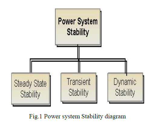 |
| The ability of a power system to maintain stability under continuous small disturbances is termed as Dynamic Stability (also known as small-signal stability). These small disturbances occur due random fluctuations in loads and at various levels of generation. In an intertwined power system, these random variations can lead to catastrophic failure as this may force the rotor angle to increase steadily. |
III. STATIC SYNCHRONOUS COMPENSATOR (STATCOM) |
| In general, STATCOM use to generate or absorb reactive power. The active power generation or absorption capability of the STATCOM is normally used under special circumstances such as to enhance the steady state and transient voltage control, to improve the sag elimination capability. |
A. BASIC OPERATION |
| The basic electronic block of the STATCOM is the voltage sourced inverter that converts an input dc voltage into a three phase output voltage at fundamental frequency. In its simplest form, the STATCOM is made up of a coupling transformer, a voltage-sourced inverter and a dc capacitor. In this arrangement, the steady-state power exchange between the device and the ac system is mainly reactive. A functional model of the STATCOM is shown in fig.2 Regulating |
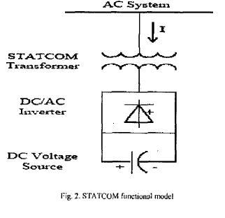 |
| Regulating the amplitude of the STATCOM output voltage controls the reactive power exchange of the STATCOM with the ac system. If the amplitudes of the STATCOM output voltage and the ac system voltage are equal, the reactive current is zero and the STATCOM does not generate absorb reactive power. If the amplitude of the STATCOM output voltage is increased above the amplitude of the ac system voltage, the current flows through the transformer reactance from the STATCOM to the ac system, and the device generates reactive power (capacitive). If the amplitude of the STATCOM output voltage is decreased to a level below that of the ac system, then the current flows from the ac system to the STATCOM, resulting in the device absorbing reactive power (inductive). Since the STA'I'COM is generating/ absorbing only reactive power, the output voltage and the ac system voltage are in phase, when neglecting circuit losses. The current drawn from the STATCOM is 90'- shifted with respect to the ac system voltage, and it can be leading (generates reactive power) or lagging (absorbs reactive power).A capacitor is used to maintain dc voltage to the inverter. An uncontrolled rectifier based six diodes used to keep the Capacitor charged to the required levels. |
B.PRINCIPLE OF REACTIVE POWER CONTROL |
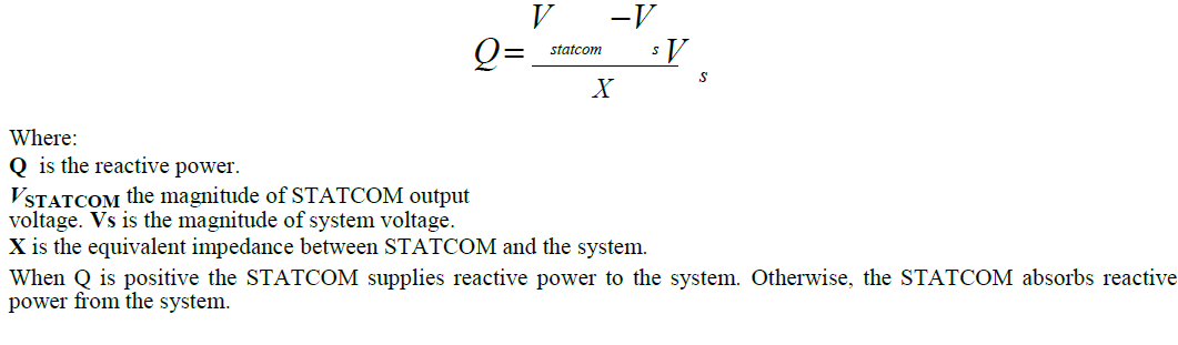
| The principle of control reactive power via STATCOM is well known that the amount of type (capacitive or inductive) of reactive power exchange between the STATCOM and the system can be adjusted by controlling the magnitude of STATCOM output voltage with respect to that of system voltage. The reactive power supplied by the STATCOM is given as: |
 |
IV.SIMULATION AND RESULTS OF MULTIMACHINE SYSTEM |
| The popular Western System Coordinated Council (WSCC) 3-machines 9-bus practical power system is a widely used one and very frequently used Fig.3 shows a 3-machines 9-bus WSCC system. Here the loads have been assumed to be represented by constant impedance model. |
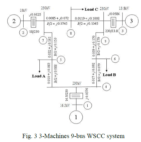 |
| The base MVA of the system is 100, and system frequency is 60 Hz. All time constants are in seconds. The complete system with all the required components has been modeled by using MATLAB/Simulink blocks. |
A. RESULTS |
| Case 1- MATLAB/Simulink model of multi-machine (3-machine 9-bus) WSCC system, is incorporated with a three-phase fault and without STATCOM. For transient Stability studies, the variation of relative angular positions of the generators with time has been analyzed. The relative angular positions of the rotor are calculated as given below: |
| del 2_1 = del 2-del 1 |
| del 3_2 = del 3-del 2 |
| del 3_1 = del 3- del 1 |
| Where del 1, del 2and del 3 are the rotor angle for generators M1, M2 and M3 |
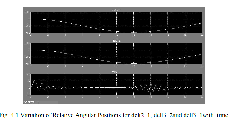 |
| Fig.4.1 shows the variation of relative angular positions with time for 3-machine 9-bus system with a three-phase fault between bus 9 and bus 4. Due to the fault, the system goes to instability. The total simulation time taken is 20 sec. |
| Case 2- The MATLAB/Simulink model of 3-machine 9-bus WSCC system with a three-phase fault occurring between bus 9 and bus 4 and STATCOM placed between bus 9 and bus 4. For transient stability, the variation of relative angular positions with time is been analyzed. The total simulation time taken is 20 sec. |
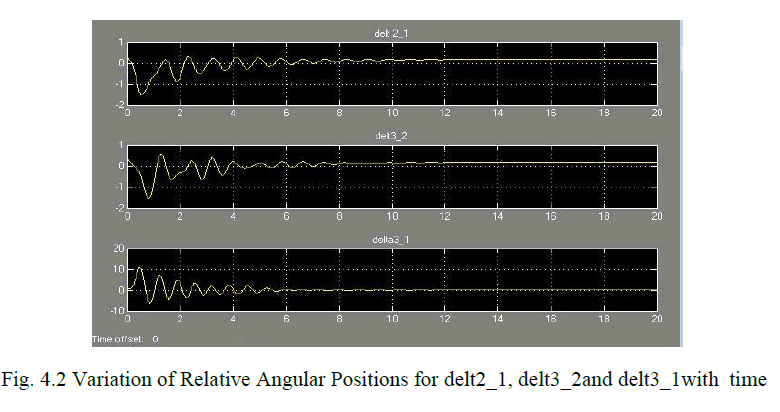 |
| Fig.4.2 shows the variation of relative angular positions with time for 3-machine 9-bus system with a three-phase fault between bus 9 and bus 4. |
| The position of STATCOM has been analyzed to study the optimum location of STATCOM in case of a fault in a system and the time taken to attain stability for three relative angular positions delt2_1, delt3_2 and delt3_1. The total simulation time taken is 20 sec. |
V.CONCLUSION |
| The stability improvement of the multi-machine power system at different fault condition is investigated in this paper. When a three-phase fault is between bus 9 and bus 4 and without STATCOM. Due to the fault, the system goes to instability. When three-phase fault occurring between bus 9 and bus 4 and with STATCOM, then the STATCOM finds its best location in the midpoint of the same line i.e. between bus 9 and bus 4. Thus system gets stable very fast as compare to other locations of STATCOM for the same case. The simulation of multi-machine (3-machine 9-bus) WSCC system with STATCOM FACTS controller has been done using MATLAB/Simulink software. This simulation can also be extended for multiple faults system and Complex multi-machine systems. |
References |
|