ISSN ONLINE(2278-8875) PRINT (2320-3765)
ISSN ONLINE(2278-8875) PRINT (2320-3765)
P.Suman Pramod Kumar 1, N.Vijaysimha2, C.B.Saravanan3
|
| Related article at Pubmed, Scholar Google |
Visit for more related articles at International Journal of Advanced Research in Electrical, Electronics and Instrumentation Engineering
This paper presents the schematic and basic controls of a reconfigurable FACTS system that can be used to realize the major voltage source converter FACTS topologies: STATCOM, SSSC and UPFC. Furthermore, the state models and control algorithms for the FACTS devices are proposed. A Digital Signal Processor (DSP) is used to implement the control system for these devices. The comparison of the experimental and simulation results is also provided to verify the proposed controls and also it describes an active approach to series line compensation, in which a synchronous voltage source, implemented by a gate turn-off(GTO) based voltage sourced inverter, is used to provide controllable series compensation. This compensator, called static synchronous series compensator(SSSC),can provide controllable compensating voltage over an identical capacitive and inductive range, independently of the magnatude of the line current. It is immune to classical network resonances. In addition to series reactive compensation, with an external DC power supply it can also compensate the voltage drop across the resistive component of the line impedence. The compensation of the real part of the impedence can maintain high X/R ratio even if the line has a very high degree of series compensation. Concurrent and coordinated modulation of reactive and real compensation can greatly increase power oscillation damping. The paper discusses the basic operating and performance characteristics of the SSSC, and compares them to those characterizing and more conventional compensators based on thyristor-switched or controlled series capacitors. It also presents some of the results of TNA simulations carried out with an SSSC hardware model. presented an in-depth investigation of the dynamic performance of STATCOM and SSSC theoretically and by exact digital simulation. A 24- pulse GTO based converter model is designed to represent the operation of the STATCOM and SSSC within a power transmission system. It is shown that the Phase-Locked Loop (PLL) inherent delay has a great effect on the dynamic operation of the SSSC and a new auxiliary regulator is proposed to enhance the dynamic performance of the SSSC. The proposed control schemes are validated by digital simulation.
Keywords |
| compensation ,facts,voltage,stability |
INTRODUCTION |
| Without electricity, modern society would cease to function. As the volume of power transmitted and distributed increases, so do the requirements for a high quality and reliable supply. At the same time, rising costs and growing environmental concerns make the process of building new power transmission and distribution lines increasingly complicated and time-consuming. Making existing lines as well as new ones more efficient and economical, then becomes a compelling alternative. Optimum power transmission and distribution also entails the reduction of transfer losses and provision of adequate power quality and availability at the receiving end. The purpose of transmission network is to pool power plants and load centers in order to minimize the total power generation capacity and fuel cost. In general, if a power delivery system was made up of radial lines from individual local generators without being part of a grid system, more generation sources would be needed to serve the load with same reliability and the cost of electricity would be much higher. In this point of view, transmission is an alternative to a new generation resources. As power transfer grow, the power system becomes increasingly more complex to operate and the system become less secure. It may lead to large power flows with inadequate control, excessive reactive power in various parts of the system and large dynamic swings between different parts of the system, thus the full potential of transmission interconnections cannot be utilized. Assuming that sufficient generated power is available, the challenge is to ensure the reliable operational performance of the delivery system, Reliable system operation requires coordinated management of both generation and transmission assets, since the pattern of generation strongly influences “loadabilityâÃâ¬ÃŸ of the transmission lines. Restructuring has greatly reduced the degree to which grid operators can manage the generation side of the relationship, so the emphasis here is upon enhanced system performance through improvements in transmission capabilities alone |
A. Principles of the Series Controllers |
| If the line voltage is in phase quadrature with the line current, the series controller absorbs or produces reactive power, while if it is not, the controllers absorbs or produces real and reactive power. Examples of such controllers are Static Synchronous Series Compensator (SSSC), Thyristor-Switched Series Capacitor (TSSC), Thyristor-Controlled Series Reactor (TCSR), to cite a few. They can be effectively used to control current and power flow in the system and to damp systemâÃâ¬ÃŸs oscillations. Among these Static Synchronous Series Compensator (SSSC) is one of the important series FACTS devices. SSSC is a solid-state voltage source inverter, injects an almost sinusoidal voltage, of variable magnitude in series with the transmission line. The injected voltage is almost in quadrature with the line current. A small part of the injected voltage, which is in phase with the line current, provides the losses in the inverter. The applications of the SSSC are 1)To control the power flow, 2) To increase the power transfer limits, 3). To improve the transient stability 4) To dampen power system oscillations, 5) To dampen Sub-Synchronous Resonance (SSR). |
B. Principles of the Shunt Controllers |
| Shunt controllers are similar to the series controllers with the difference being that they inject current into the system at the point where they are connected. Variable shunt impedance connected to a line causes a variable current flow by injecting a current into the system. If the injected current is in phase quadrature with the line voltage, the controller adjusts reactive power while if the current is not in phase quadrature, the controller adjusts real power. Examples of such systems are Static Synchronous Generator (SSG), Static Var Compensator (SVC). They can be used as a good way to control the voltage in and around the point of connection by injecting active or reactive current into the system. |
C. Principles of the Combined Series-Series Controllers |
| A combined series-series controller may have two configurations. One configuration consists of series controllers operating in a coordinated manner in a multiline transmission system. The other configuration provides independent reactive p0ower control for each line of a multiline transmission system and, at the same time, facilitates real power transfer through the power link. An example of this type of controller is the Interline Power Flow Controller (IPFC), which helps in balancing both the real and reactive power flows on the lines. |
D. Principles of Combined Series-Shunt Controllers |
| A combined series-shunt controller may have two configurations, one being two separate series and shunt controllers that operate in a coordinated manner and the other one being interconnected series and shunt components. In each configuration, the shunt component injects a current into the system while the series component injects a series voltage. When these two elements are unified, a real power can be exchanged between them via the power link. Examples of such controllers are UPFC and Thyristor- Controlled Phase-Shifting Transformer (TCPST). These make use of the advantages of both series and shunt controllers and, hence, facilitate effective and independent power/current flow and line voltage control. |
| Figure 1 Representation of different fact controllers |
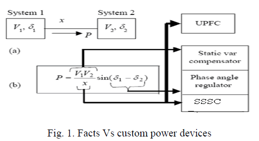 |
| The twin concepts of Flexible Alternating Current transmission Systems (FACTS) and Custom Power emerged from the Electric Power Research Institute (EPRI) Palo Alto, CA in the late1980's. Ever since, both technologies have attracted great interest from equipment manufacturers, utilities and university research establishments. FACTS use the latest power electronic devices and methods to control electronically the high-voltage side of the network Custom Power focuses on low-voltage distribution, and it is a technology born in response to reports of „poor powerâÃâ¬ÃŸ quality and reliability of supply affecting factories, offices and homes. With Custom Power solutions in place, the end-user will see tighter voltage regulation, near-zero power interruptions, low harmonic voltages, and acceptance of rapidly fluctuating and other non-linear loads in the vicinity. The fruits of fully matured FACTS and Custom Power technologies are many and yet the issues to be resolved, at this point in time, are even greater. Once the incorporation of the new technology takes place in earnest, an increase in operational complexity is expected. The principle being to provide a “Total solution” strategy comprising more than one device coupled with software to achieve power control at the transmission level and signal conditioning at the distribution level.Facts are primarily concerned with the control of power flow from generator to user. The use of fact devices helps increase in transmission capability by operating closer to the thermal limit. Because these devices effectively control the impedance of the lines, power can be directed along the desired paths reducing the „strainâÃâ¬ÃŸ on certain networks during peak demand. Some of the FACTS devices are SVC, STATCOM and UPSC etc |
| E. Compensating type |
| These devices protect the load from the source, |
| 1. Static Transfer Switch (STS) |
| 2. Static Voltage Regulator (SVR) |
| 3. Distribution Static Compensator (DSTATCOM) |
| 4. Dynamic Voltage Restorer (DVR) |
| 5. Unified Power Quality Conditioner (UPQC) |
II. SCOPE OF THE WORK |
| In this paper, simulation of various aspects of SSSC, which are power oscillation damping, improving transient stability and dynamic stability and the way to implement DVR with different control strategies in the MATLAB, simulink using Simpower systems tool box and to verify and compare the results through various case studies applying different loads and study them in detail.These simulations are used for designing the system and its controllers, and also used to evaluate the performance of it. In order to fully understand how to effectively incorporate FACTS devices into existing power systems, hardware prototype verification is necessary in addition to software simulation. Experimental studies provide valuable data to evaluate models, test proposed control algorithms, and analyze dynamic performance. Furthermore, experimental studies provide the basis with which to predict the device performance in the actual power system operation. |
III. LITERATURE REVIEW |
| It gives the information that we found related to our paper after referring to many articles and papers published by eminent personalities. A survey of the relevant papers has been done for understanding the background and concepts of load and line compensation using custom power devices and FACTS controllers. A few of them are discussed in brief. This chapter also concludes the conclusions that are reached based on our survey and problems with the conventional method of load compensation and line compensation using power electronic components in the power transmission system and instead replacing them with custom power devices like DVR can overcome the drawbacks of the conventional methods and to develop a more efficient method of compensation. |
IV. CONVENTIONAL SYSTEM SOLUTION TO REDUCE TRANSMISSION CONSTRAINTS AND DISTRIBUTION CONSTRAINTS |
| > Series Capacitors (X) |
| > Switched Shunt-Capacitors and Reactors (V) |
| > Phase Shifting Transformers (δ) |
| > Synchronous Condensers (V) |
| > Special Stability Controls (V, P, or X) |
V. STATIC SYNCHRONOUS SERIES COMPENSATER |
| Static Synchronous Series Compensator (SSSC) is one of the important series FACTS devices. SSSC is a solid-state voltage source inverter, injects an almost sinusoidal voltage, of variable magnitude in series with the transmission line. The injected voltage is almost in quadrature with the line current. A small part of the injected voltage, which is in phase with the line current, provides the losses in the inverter. Most of the injected voltage, which is in quadrature with the line current, emulates an inductive or a capacitive reactance in series with the transmission line. This emulated variable reactance, inserted by the injected voltage source, influences the electric power flow through the transmission line. |
A. Operating principle |
| A SSSC operated with out an external electric energy source as a series compensator whose output voltage is in quadrature with, and controllable independently of, the line current for the purpose of increasing or decreasing the overall reactive voltage drop across the line and thereby controlling the transmitted active power. The SSSC may include transiently rated energy storage or energy absorbing devices to enhance the dynamic behavior of the power system by additional temporary real power compensation, to increase or decrease momentarily, the overall resistive voltage drop across the line. |
 |
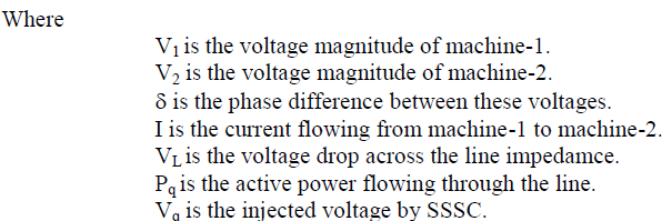 |
| The SSSC injects the compensating voltage in series with the line irrespective of line current. The transmitted power Pq versus the transmission angle ïÃÂä relationship therefore becomes a parametric function of the injected voltage, Vq, and it can be expressed for a two machine system as follows: |
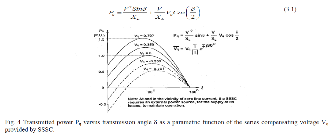 |
| The fig. 3.3 shows that the SSSC increases or decreases the transmitted power by a fixed fraction of the maximum power transmittable by the uncompensated line, independently of ïÃÂä in the important angle range of 0 ïÃâã ïÃÂä ïÃâã 90ïÃâð. Furthermore, if this injected voltage is made larger that the voltage impressed across the uncompensated line by the sending and receiving end systems, then the power flow will reverse, as indicated in fig. 3.3. |
B. Modeling of three phase three level 48-pulse VSI |
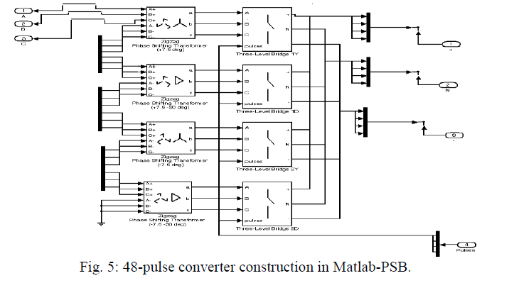
| The inverter used in SSSC is a 48-pulse GTO converter. It consists of four 3-phase, 3-level inverters and four phase-shifting transformers as shown in fig. 3.4. The DC bus is connected to the four 3-phase inverters. The four voltages generated by the inverters are applied to secondary windings of four zig-zag phase-shifting transformers connected in Wye (Y) or Delta (D). The four transformer primary windings are connected in series and the converter pulse patterns are phase shifted so that the four voltage fundamental components sum in phase on the primary side. The inverter requires 4 pulses per arm. The pulse pattern sent to each leg of a 3-phase inverter is described in fig. 3.5. The phase shifts produced by the secondary delta connections (-30 degrees) and by the primary zig-zag connections (+7.5 degrees for transformers 1Y and 1D, and -7.5 degrees for transformers 2Y and 2D) allows to neutralize harmonics up to 45th harmonic, as explained below: The 30-degree phase-shift between the Y and D secondaries cancels harmonics 5+12n (5, 17, 29, 41, ...) and 7+12n (7, 19, 31, 43, ...). In addition, the 15-degree phase shift between the two groups of transformers (1Y and 1D leading by 7.5 degrees, 2Y and 2D lagging by +7.5 degrees) allows cancellation of harmonics 11+24n (11, 35, ...) and 13+24n (13, 37, ...). Considering that all 3n the harmonics are not transmitted by the Y |
 |
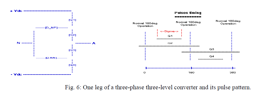 |
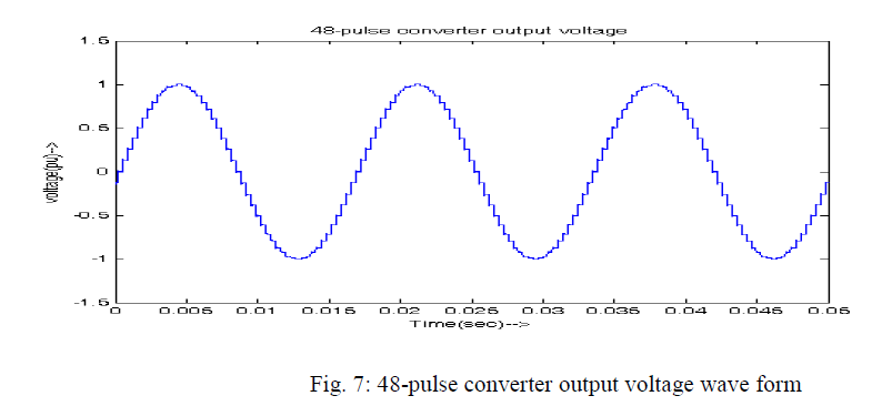
| and D secondaries, the first harmonic which are not cancelled by the transformers are 23rd, 25th, 47th and 49th. By choosing an appropriate conduction angle for the 3-level inverters (sigma = 180 - 7.5 = 172.5 degrees), the 23rd and 25th can be minimized. The first significant harmonics are therefore the 47th and 49th. Its almost sinusoidal. |
 |
C. Conventional PI controller for SSSC |
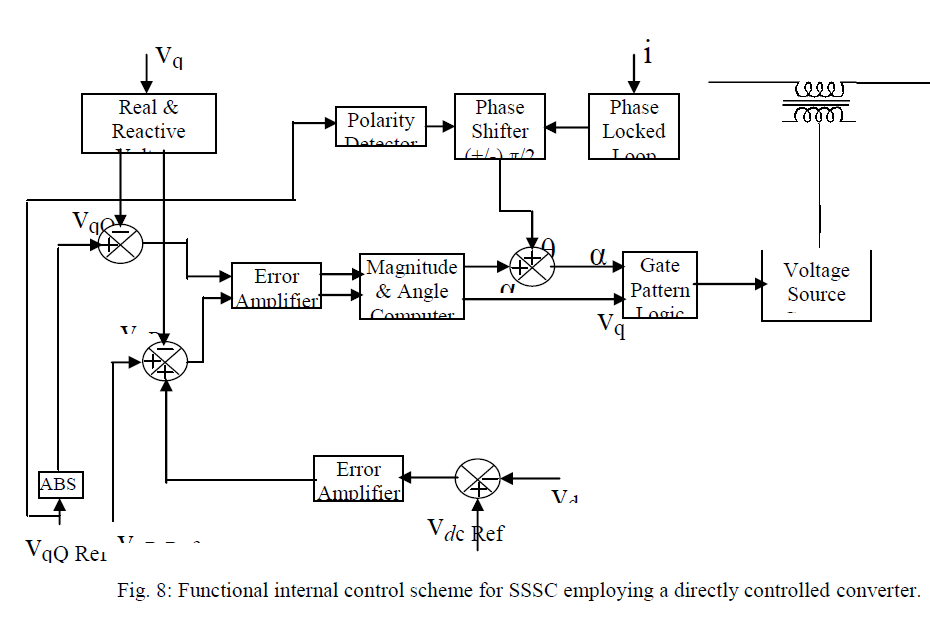
| The synchronization to the line current is accomplished by Phase-Locked Loop (PLL), and after a phase shifting of 90ïÃâð (leading or lagging) will give synchronization angle, ïÃÂñ. The control is operated from three reference signals: VqQRef , defining the desired voltage magnitude of the series reactive compensating voltage; the optional VqRRef , defining the desired magnitude of series real compensating voltage; and the VdcRef , defining the operating voltage of the dc capacitor. The reactive reference voltage VqQRef and the overall real voltage reference VqRRef + VdcRef are compared to the corresponding components of the measured compensating voltage Vq. From the resulting signals the magnitude of Vq and its angle ïÃÂá with respect to ïÃÂñ are derived. The magnitude, Vq and the angle, ïÃÂñ + ïÃÂá are then used to generate the gate drive signals for the converter. |
 |
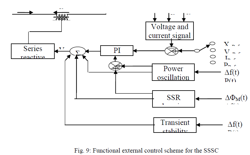
| The external control scheme, which defines the functional operation of the compensator and derives the reference input for it, is shown in fig. 4.2. These functional operations are power flow control, improvement of transient and dynamic stability and damping of sub-synchronous resonance. Power flow control, transient and dynamic stability improvement and SSR mitigation with SSSC will be explained in next chapters. The main power flow control is executed by a closed loop, which is operated from one of the selected references XqRef, or VqRef, or I Ref, or P Ref. The corresponding network variable is derived (Xq, or Vq, or I, or P) by the voltage and current processor and compared to the selected reference. The amplified error at the output of the PI controller provides the reference, Xq, or Vq, for the internal controller. The auxiliary controls signals to improve transient and dynamic stability, and to damp sub-synchronous oscillations, are derived from the relevant system variables, such as system frequency variation, or power flow variation, or from torsional speed variation. A fuzzy precompensated PI controller for SSSC will be explained in the next section. |
 |
VI. IMPROVEMENT OF TRANSIENT STABILITY AND DYNAMIC STABILITY BY SSSC |
A. Operating principle |
| The improvement of transient stability with SSSC can be explained in the simple two machine system by equal area criteria. Consider the two machine system with and with out SSSC compensation. Assume the systems with and without SSSC compensation are subjected to the same fault for the same period of time. Both systems are transmitting equal power (Pm) before the fault occurs at angles ïÃÂä1 and ïÃÂäs1 respectively. The dynamic behavior of these systems is illustrated in fig.5.1. |
 |
 |
| Comparison of these two figures clearly shows a substantial increase in the transient stability margin in the system with SSSC. |
| Controlled series compensation can be applied effectively to damp power system oscillations. For power oscillation damping it is necessary to vary the applied compensation so as to counteract the acceleration and decelerating swings on the disturbed machines. That is, when the rotationally oscillating generator accelerates and angle δ increases ( |
B. Modelling and simulation |
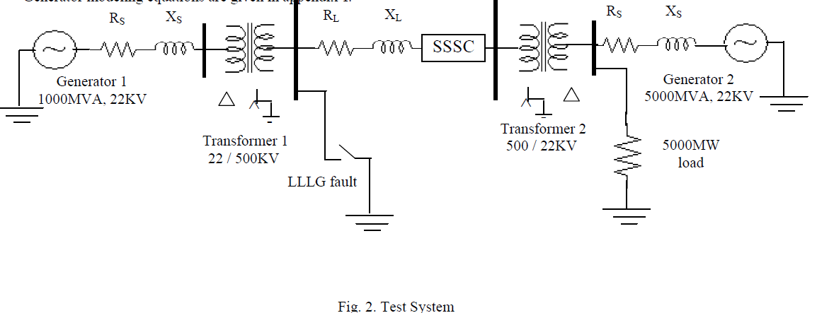
| The test system consists of a 1000 MVA hydraulic generation plant (generator-1) is connected to a load center through a long 500 kV, 700 km transmission line. The 5000 MW resistive load is connected as shown in fig. 5.2. The load is fed by the remote 1000 MW plant and a local generation of 4000 MW (generator-2). The system has been initialized so that the line carries 950 MW. The two machines are equipped with a Hydraulic Turbine and Governor (HTG), Excitation system and Power System Stabilizer (PSS). The construction of the entire system in Matlab-PSB is given in fig. 5.3. Generator modeling equations are given in appendix-I. |
 |
VIII. CONCLUSION |
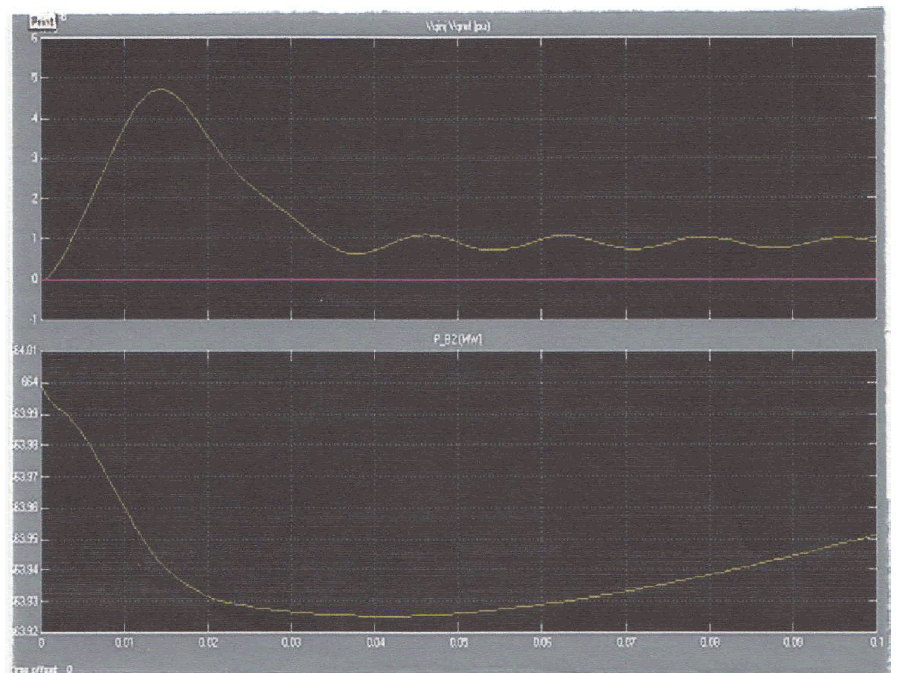
| In this paper, simulation of various aspects of Static Synchronous Series Compensator (SSSC), which are , power oscillation damping, improving transient stability done in Matlab-Power System Blockset (PSB). Improvement of transient stability and dynamic stability by SSSC is explained. A two machine test system is taken and a LLLG fault is created. This situation is simulated in Matlab-PSB, and results are showing that, when the system is incorporated with SSSC, the system is not losing its synchronism and is stable. But with out SSSC, the system is losing its synchronism and is unstable. This shows the capability of SSSC in improving the transient stability margin of a power system. In the above test system, a LG fault is created and cleared after 6 cycles. This situation is also simulated in Matlab-PSB. From these simulation results, we can observe the capability of SSSC in damping power system oscillations.Power flow control by 48-pulse VSI based SSSC simulated. From these simulation results, it is shown that SSSC is very effective in controlling the power flow, and the response time of it is also very fast. |
IX. SCOPE OF FUTURE WORK |
| ïÃÆÃË Hardware implementation of SSSC for closed loop control of power has to be done. |
| ïÃÆÃË Designing a damping controller for mitigation of Subsynchronous Resonance (SSR). |
X. SIMULINK RESULTS |
 |
References |
|