International Journal of Advanced Research in Electrical, Electronics and Instrumentation Engineering
ISSN ONLINE(2278-8875) PRINT (2320-3765)
ISSN ONLINE(2278-8875) PRINT (2320-3765)
K. Sowjanya, Prof., P.Sangameshwara Raju
|
| Related article at Pubmed, Scholar Google |
Visit for more related articles at International Journal of Advanced Research in Electrical, Electronics and Instrumentation Engineering
Improve in power consumption cause serious balance issues in electrical power systems if there are no ongoing or upcoming development tasks of new power plants or transmission lines. Additionally, such increase can result in large energy failures of the system. In expensive and ecologically effective way to prevent building the new infrastructures such as power plants, transmission lines, etc., the distributed generation (DG) has been compensated great attention.
Keywords |
| Distributed generation, grid connection, Kalman filter algorithm, load-concentration-bus, optimal location, optimal size, power loss |
INTRODUCTION |
| IN response to the recently improved prices of oil and natural gas, it is expected that the electrical energy industry will go through significant and fast change with regard to its framework, function, preparing, and control. Moreover, because of new restrictions placed by cost-effective, governmental, and ecological factors, styles in power system preparing and function are being forced toward maximum usage of current power facilities with limited working edges[2]. Therefore, the electrical powered power companies are attempting to achieve this purpose via many different ways, one of which is to delay the distribution generation (DG) remedy by a separate energy manufacturer (IPP) to meet growing customer fill demand. In this case, deferral attributes obtained by the IPP rely on the step-by-step system stability enhancement made by the DG remedy[1]-[4]. The DG is based on the alternative energy such as energy cell, photovoltaic or PV and wind energy as well as mixed heat and energy gas generator, micro-turbine, etc. Now, it becomes an essential important component of the modern energy system recently for several reasons. |
II.ELECTION OF OPTIMAL LOCATIONS |
A. Reduction of Power Loss by Connecting DG |
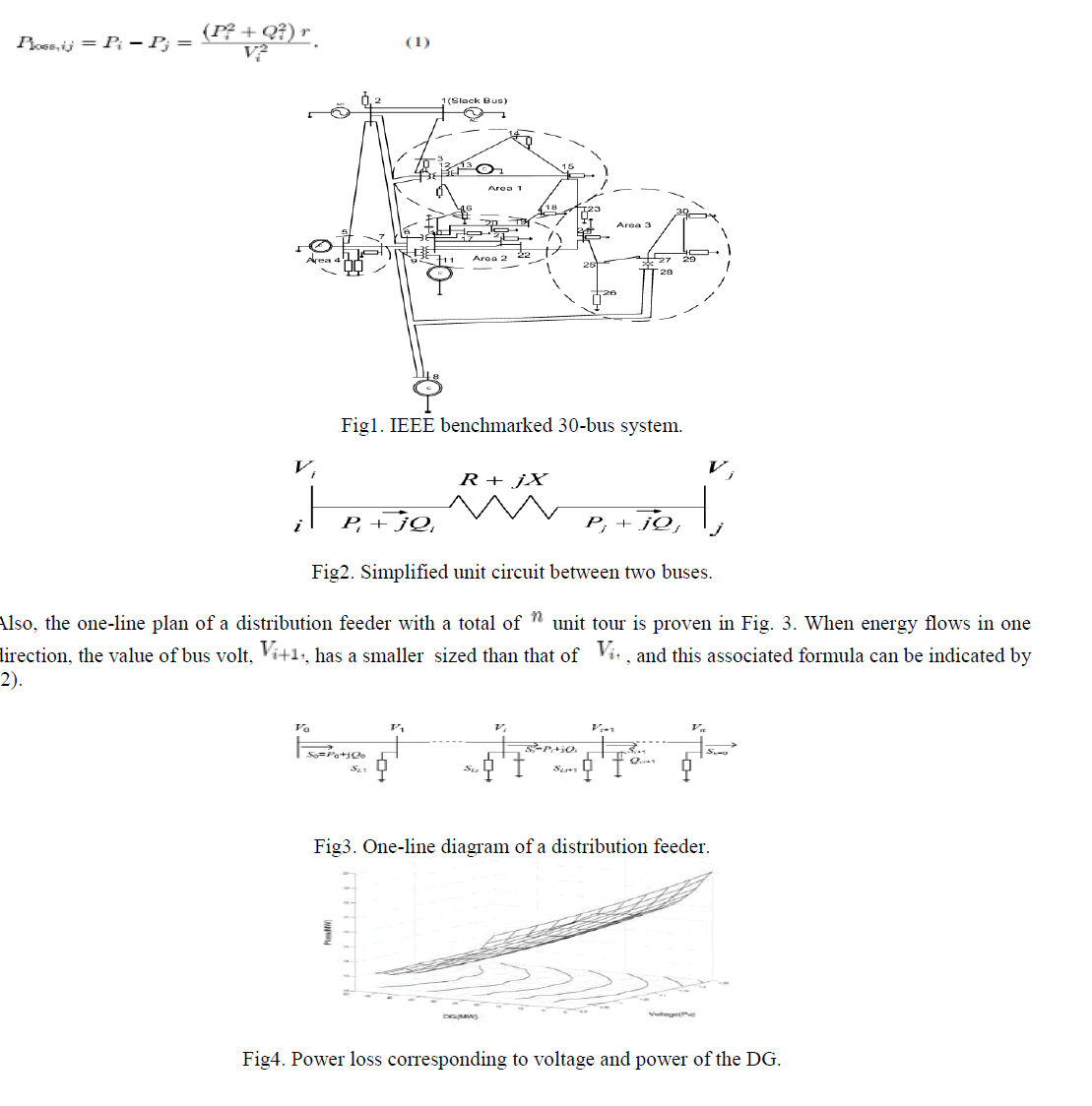
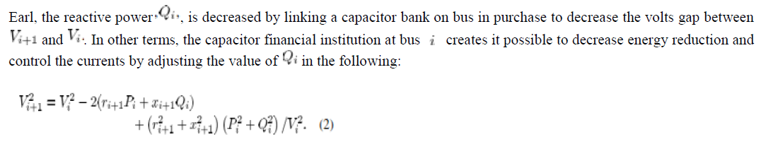
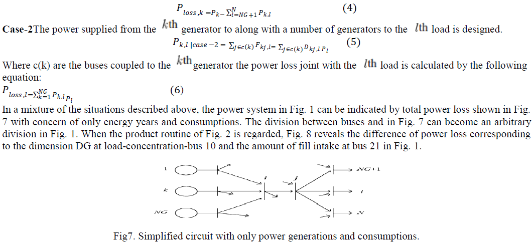
| In general, the presented power plants tend to be far from the consumption regions, and this situation causes a large amount of power loss on the power system. The IEEE benchmarked 30-bus system is shown in Fig. 1, The directly-connected-bus is defined as a bus connected to a location bus that does not pass through any other buses. For example, buses 12, 14, 18, and 23 in Fig. 1 are the directly-connected-buses if bus 15 is chosen as a reference bus. The load-concentration-bus handles relatively large loads, and Is more linked to the other directly-connected-buses when compared to other nearby buses. In Fig. 1, buses 10, 12, 27, and 5 can be selected as the delegate load-absorption buses of Areas 1 through 4, respectively. Then, they provide an effect similar to the case where there are all DGs on each load bus, but with added benefit of reduced power loss From the Simplified unit circuit shown in Fig. 2, the power loss, between two buses, and , is computed by the following: |
 |
 |
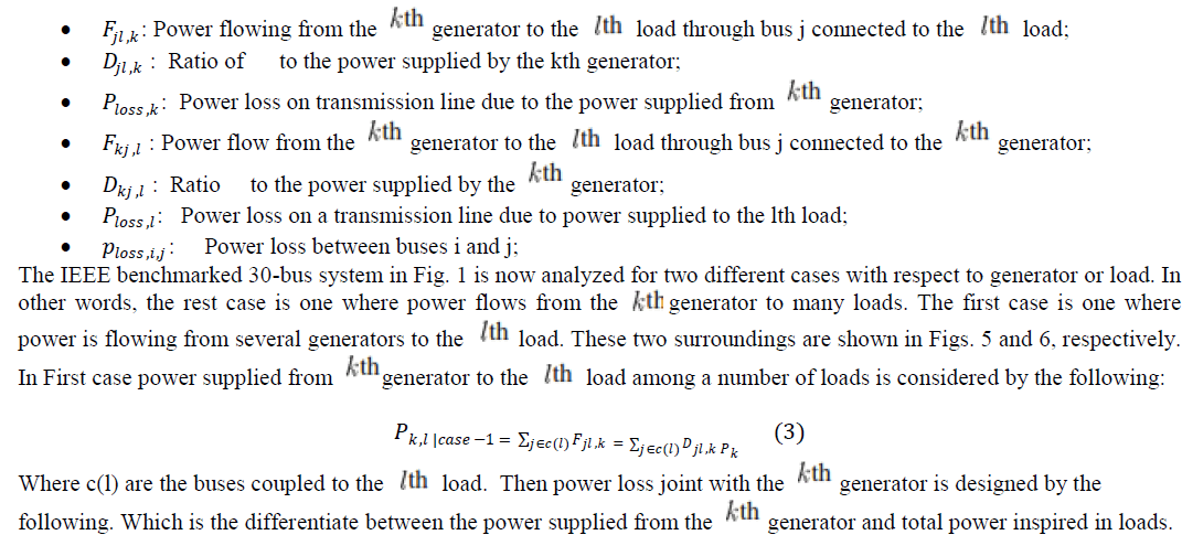
| If a DG is set up at the place of the capacitor financial institution, the proper delicate energy management of the DG has the same effect on the system as does the capacitor financial institution. Fig. 4 reveals the system power loss corresponding to the different energy and volts machines of the DG at the load-concentration-bus 10 in Place 2 of Fig. 1. It is noticed that the power loss is decreased almost linearly as the dimension DG improves. |
| B. Choice of Maximum Place for DGs by Considering Power Loss Before drawing the equations necessary to choose the optimal location for the DG, the following conditions is firstly defined. |
 |
 |
 |
III.PROCEDURE TO SELECT OPTIMAL SIZE OF MULTIPLE DGS USING KALMAN FILTER ALGORITHM |
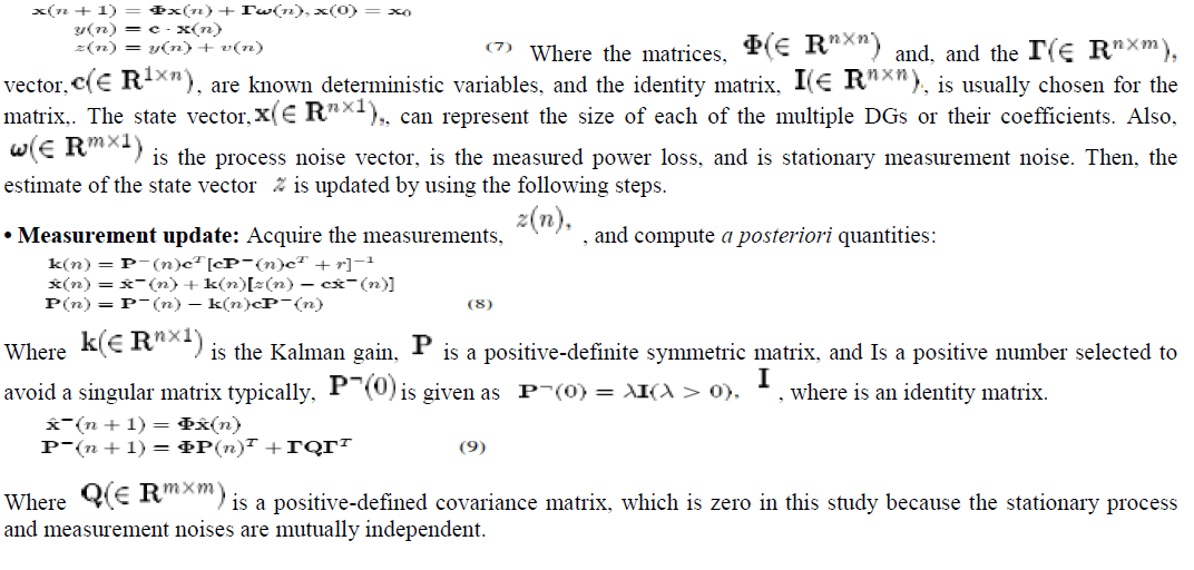
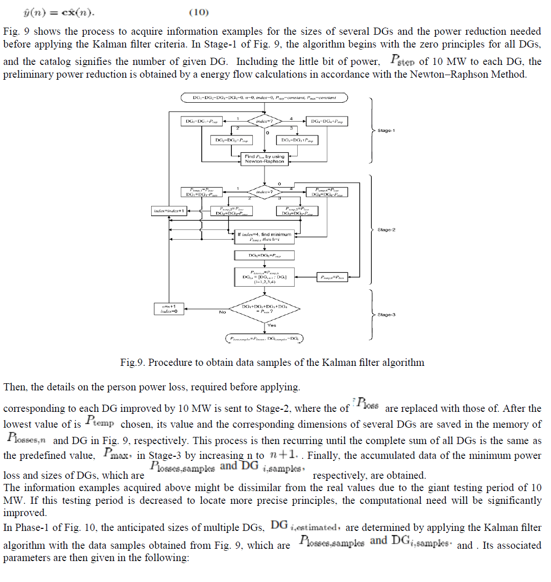
| The quantity of power consumption each area could be selected as the optimal values for the DGs to be placed. However, these are not maximum principles for the DGs because the power reduction in lines linking two buses is ignored. The Kalman filter criteria have the removing properties and the disturbance being rejected ability effective to the process and statistic sounds. In realistic surroundings (in which the declares are motivated by procedure disturbance and statement is made in the existence of statistic noise), |
 |
| Time increment: Increment and repeat. Thereafter, the estimated output (the total power loss of the system) is calculated as |
 |
 |
Future scope: |
| In future we have to find out the cost function. Depending up on the cost function of dispatchable DGs used. |
IV.SIMULATION RESULTS |
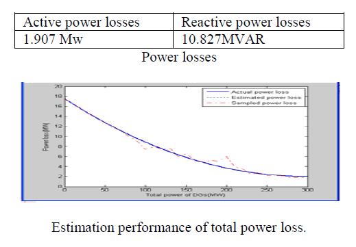 |
V.CONCLUSION |
| This document suggested the means for choosing the maximum locations and sizes of multiple distributed generations (DGs) to minimize the complete power lack of system. To cope with this optimization problem, the Kalman filter criteria were used. When the maximum dimensions of several DGs are chosen, the computation efforts might be significantly improved with many data Samples from a large-scale power system because the entire system must be examined for each information example. The proposed procedure in accordance with the Kalman filter criteria took the only few examples, and therefore decreased the computational requirement dramatically during the marketing process. |
References |
|