ISSN ONLINE(2278-8875) PRINT (2320-3765)
ISSN ONLINE(2278-8875) PRINT (2320-3765)
Praveen Kumar Nambisan.T.M1, Dr.B.N.Sarkar2
|
| Related article at Pubmed, Scholar Google |
Visit for more related articles at International Journal of Advanced Research in Electrical, Electronics and Instrumentation Engineering
This paper presents modelling and numerical simulation as well as prototype for speed control of DC series motor using a DC chopper. The pulse-width modulation method of control of semiconductor devices can help in controlling the output voltage of DC drives in turn controlling the speed for a wide range. The system is modelled and simulated to study the transient and steady state behaviour. Pulse-width modulation is a widely used technique for control of power converters and motors. The hardware model of the proposed system is built in the laboratory and experimentally to examine the system. The simulation results and experimental results are found to be in good agreement.
Keywords |
| DC series motor, DC chopper, semiconductor devices, pulse-width modulation. |
INTRODUCTION |
| Speed control of electrical motors is an old but evergreen topic in industries. With the advent of power electronic devices vis. IGBT, MOSFET etc., which can handle large amount of power at higher voltages and current magnitudes, a revolution has come on the speed control of electrical motors. With the introduction of microcontrollers, very accurate and sophisticated speed control of motors is feasible. Previous mechanical control of motors is completely overtaken by these power electronic devices. |
| Nowadays a very minute variation of speed variation can be done in a fraction of second; thereby it increases the quality of production. These power electronic controlled motors not only used in large industries like steel plants, paper plants, cement mills etc. but also for several domestic application such as grinders, mixer etc. Even the power electronics plays vital role for toy motors. For traction application IGBT/MOSFET controlled DC series motors are extensively used. |
II. LITERATURE SURVEY |
| DC-DC converters are now used for all industrial purposes and domestic purposes. With the advancement in the power electronic devices technology speed control using these devices is widely used for all the motors.The paper1describes the speed control of AC series motor using AC chopper. Since the series motor can be operated in both AC & DC, these are very convenient for specific application. Since AC choppers like inverters are used harmonic distortion occurs and power factor correction circuits are necessary which increases overall system size and cost. DC chopper system has operational benefits such as fast dynamic response and near unity line power factor.It is observed that power electronic devices play vital role in speed control of three phase induction motors( both squirrel cage and wound-type), single phase induction motor, DC shunt motors but almost no literature available on speed control of DC series motor using power electronic devices. Therefore it is thought to develop a converter controlled DC series motor. Smooth variation of speed is obtained which was never attempted until now. |
III.SYSTEM MODEL |
| Fig.1 shows the schematic diagram of the system. The system consists of DC chopper, DC series motor, speed sensor and microcontroller based drive circuit. |
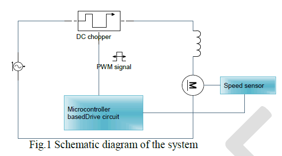 |
| In Fig.1, the DC series motor is energized by a DC chopper which in turn connected to the mains supply. The AC main voltage is rectified by a bridge rectifier to unregulated DC and given to the chopper. The output voltage of the chopper controls the speed of the motor. The driver circuit consists of microcontroller which control the duty cycle of the chopper switches. |
| DC choppers otherwise known as DC-DC converters are very efficient than linear voltage regulators. So choppers are being used in all the applications for smooth controlling of the output voltage. |
IV.DC CHOPPER |
| DC chopper is basically a dc-dc converter which converts a fixed dc voltage to variable dc. The Switched Mode Power Supplies (SMPS) in the market comprises of a cuk, a buck-boost, a front-end rectifier, a single-ended primary inductance converter (SEPIC) and a flyback converter. The above converters are suitable for low to medium range power ratings. SEPIC, buck-boost and cuk topologies are used where the output voltage should be either higher than or lower than the input. Among these, a single switch SEPIC is very efficient and easy to control with a non-inverted output voltage. |
| In this paper SEPIC topology is used to build the DC chopper. Low ESR capacitors and fast recovery or schottky diodes are used for increasing the efficiency. |
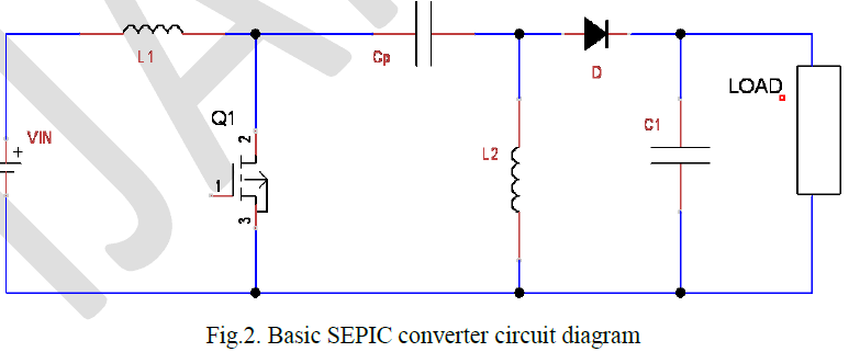 |
| Fig.2 shows the basic SEPIC converter circuit. It consists of 2 inductors L1 and L2, single power switch Q1, coupling capacitor Cp, diode D and output filter capacitor C1. |
V.OPERATION OF THE CHOPPER |
| The operation of the circuit can be explained under CCM operation. Since single switch is used, it is easy to control the gate pulses. The operation modes of the SEPIC converter can be divided into two; when the switch Q1 is ON and when the switch Q1 is OFF. So the operation stages are, |
| 1. Switch Q1 is ON: |
| The switch Q is closed and the inductor L1 starts charging from the input while capacitor Cp helps in charging the inductor L2. Thus the capacitor Cp charges to supply the voltage VIN. So here the instantaneous voltage VL1 is equal to VIN, while the voltage VL2 will be equal to –VIN. |
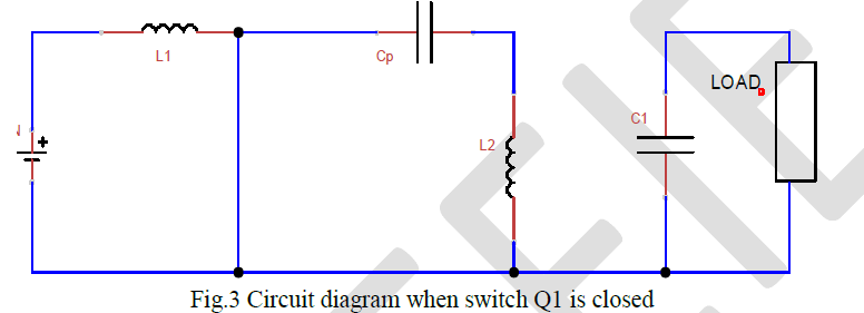 |
| Fig.3 shows the circuit diagram when the switch Q1 is turned ON. The diode acts as open circuit, thus no current pass through it. |
2. Switch Q1 is OFF: |
| During this condition, switch Q1 is open, thus the current thourgh L1 and Cp are the same. So during this condition the power needed by the load is delivered by both the inductors L1 and L2. In this mode, the capacitor Cp is charging from inductor L1 so that Cprecharges L2 during the next ON cycle. |
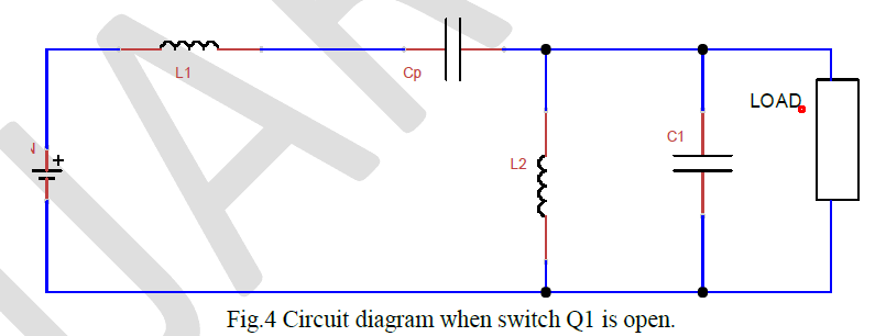 |
| Fig.4 shows the circuit diagram of SEPIC converter when the switch Q1 is OFF, thus it act as open circuit. So the current directly pass to the coupling capacitor Cp and inductor L2. |
VI. MODELLING AND SIMULATION |
| The simulation of the DC chopper driven DC series motor is carried out in MATLAB/SIMULINK. The DC series motor is first modelled using the equivalent model of the series motor and its equations. The motor is then energized by the DC chopper and the feedback consists of the speed controller as well as the current controller. |
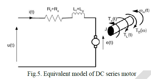 |
| Fig.5 shows the equivalent model of a DC series motor. The field and the armature are in series as shown. It includes the armature and field resistance as well as the armature and field inductance, where the inductance plays vital role in the speed control as well. This model is used to determine the transfer function used in the simulation. |
VII. RESULT AND DISCUSSION |
| The model is simulated to study the steady-state and transient behaviour of the system. Following plots are obtained and compared with the conventional motor results. |
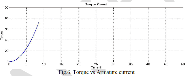 |
| Fig.6. shows the Torque vs Armature current characteristics. Since the armature and field are series in a DC series motor, we can show that, |
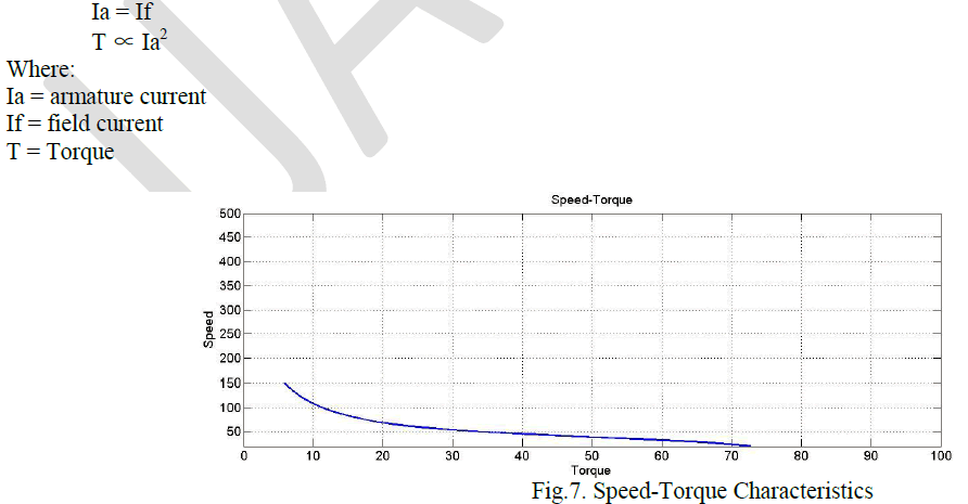 |
| Fig.7. shows the speed-torque characteristics of the DC series motor. |
| Since Ia∝√T is in linear zone, it indicates that speed approaches dangerous value in no-load condition. For this reason, a series motor is never connected to mechanical load through belt drive. If a belt snaps, the motor becomes unloaded and as a consequence speed goes up unrestricted causing mechanical damage to the motor. |
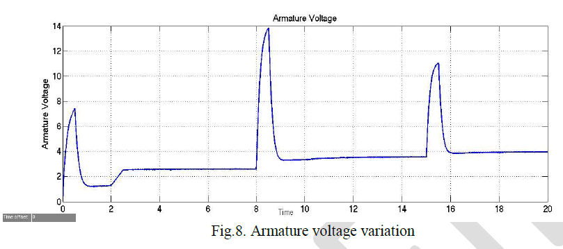 |
| Fig.8. shows the voltage variations during the operation of the system. The voltage is varied between 0-30 Volts to control the speed of the series motor. The load torque is varied in steps of the range [6.6 6.6 6.6 6.6 5 4] Nm and the reference speed is also given in step of [45 45 45 45 800 1200] rpm for the time range [0 2 4 6 8 15] sec. |
 s s |
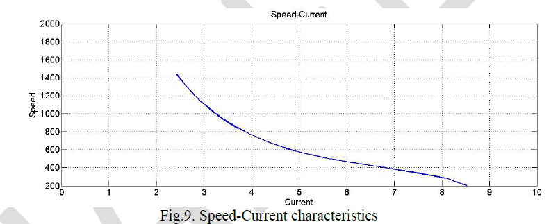
| Fig.9. shows the speed-current characteristics of the series motor. In DC series motor value of Ia (current) is a measure of degree of loading. Therefore a series motor should be never operated under no-load condition. Unlike other dc motors series motors don’t have a fine no load speed condition. |
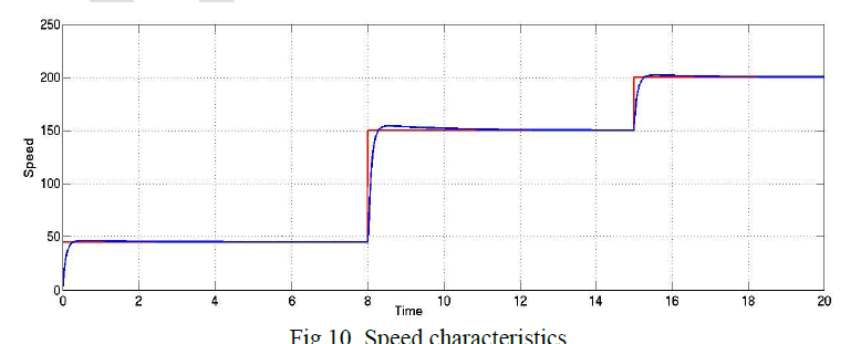 |
| Fig.10. shows the speed variation of the motor. The reference speed was given in step [45 45 45 45 150 200] for the time range [0 2 4 6 8 15]. The output speed varies accordingly maintaining the desired speed at desired time. A smooth variation like this was not achieved with previous methods of speed control in DC series motor. Mechanical control can achieve only step variation whereas this system can have a smooth control over the speed. |
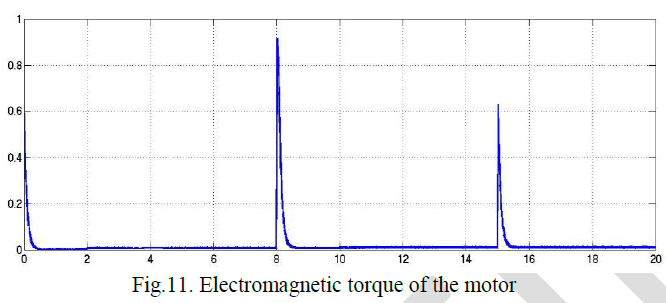 |
| Fig.11. shows the electromagnetic torque of the motor during the simulation. The change in load torque is taken in steps of the range [6.6 6.6 6.6 6.6 5 4] Nm and electromagnetic torque of the motor is plotted with respect to time. Electromagnetic torques is important in determining the amount of load the motor can withstand. The torque produced by the motor also helps in determining the torque characteristics of the motor and compare the efficiencies. |
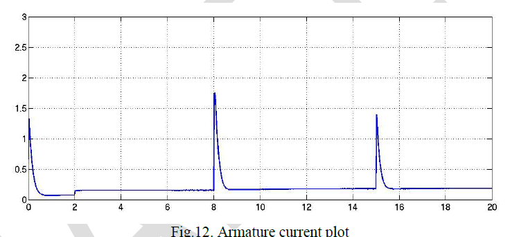 |
| Fig.12. shows the armature current characteristics. The current controller limits the armature current to the reference. Here 2A is taken as the upper limit reference. The current controller used in the simulation is a PID controller which limits the current. |
| The characteristics of the DC series motor obtained in the simulation is compared with conventional series motor plots and found that both the plots nearly match. Also the speed variation achieved is smoother than previous methods2. The armature voltage, current plots are used to determine the circuit for building the prototype. |
VIII. HARDWARE MODEL AND RESULTS |
| The hardware model of the system is built for a 30volts, 300mA DC series motor. The SEPIC converter is built using P55NF06, a 60volt/55A NPN MOSFET. The gate pulse is provided by a microcontroller PIC16f877A. The speed of motor is sensed by an emf generator and the error voltage is given to the ADC of the microcontroller. The microcontroller changes the duty cycle of the MOSFET to change the output voltage. Since DC series motor has very high torque, the motor should not run without load. So a DC generator is connected to the shaft of the DC series motor and generator is loaded. Necessary results are measured and following plots are drawn. |
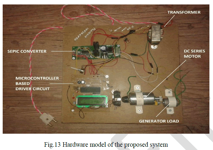 |
| Fig.13 shows the hardware prototype developed at the laboratory. The SEPIC converter is designed for the motor. It can be seen the input supply main is connected to the transformer which step down the voltage from 230volts to 24volts. An 800rpm DC generator is used as a load which can be connected to resistance box or various resistive loads such as incandescent bulbs for different load variations. |
| From the hardware experiment, the motor speed and current are measured for different voltages and varying loads.The measured results are used to plot the speed-current characteristics. It is found that the graph obtained matches with conventional motor characteristics. |
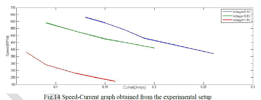 |
| Fig.14 shows the plot of speed vs current. It is seen that the curve takes an inverse characteristics and a smoother variation is achieved. It’s also seen that the no load speed goes very high, so the motor is operated only with loads. Speed reduces as well as the current increases with variation in the loads in respective operating voltages. |
IX.CONCLUSION AND FUTURE SCOPE |
| In this paper speed control of DC series motor is using a chopper is proposed. The system consists of a SEPIC chopper to control the output voltage given to the motor. The SEPIC converter consists of single MOSFET which operates in ON-OFF modes. The controlled voltage is obtained from the output of SEPIC to control the motor speed. The steadystate and dynamic behaviour of the system is studied from the simulation. The load responses of the system are predicted from the simulation model. The driver circuit and the chopper circuit are built in the laboratory to compare the simulation and the experimental results which were found to be in good agreement. |
| Future developments include use of high efficiency choppers with advanced power switches. The separate inductors can be replaced with high efficiency coupled inductors where the coils are wound on the same core. New closed loop control strategies can be included to have smooth control over the chopper voltage and current controls. |
References |
|