ISSN ONLINE(2278-8875) PRINT (2320-3765)
ISSN ONLINE(2278-8875) PRINT (2320-3765)
R.Ashik1, Dr.V.Sivachidambaranathan2
|
| Related article at Pubmed, Scholar Google |
Visit for more related articles at International Journal of Advanced Research in Electrical, Electronics and Instrumentation Engineering
In this paper, the sub synchronous resonance (SSR) for IEEE second benchmark system is investigated using Mat lab based on the Power System Block-set (PSB) in conjunction with Simulink. The effects of series compensation level and fault amount of power delivery on SSR are investigated. The main objective of this work is to study the behaviour of the SEN transformer to an induction–generator (IG) effect as well as torsional interactions (TI) in a wind farm. In order to conduct the studies, the IEEE first benchmark model on SSR is adapted with the combination of self– excited induction generator (SEIG) based wind turbine..
Keywords |
| Sen Transformer; SSR;FACTS Devise; IEEE first bench mark model |
INTRODUCTION |
| The world is getting hotter, in fact by 1°C on land over the last 100 years, and the overwhelming consensus of scientific opinion is that human activities, particularly the emission of greenhouse gasses, are the cause. The energy sector is by far the biggest source of these emissions in globally, and if we are to tackle climate change it is clear we need to move away from burning limited fossil fuel reserves to more sustainable and renewable sources of energy. Wind power is a well proven and cost-effective technology and expected to be the main way in which industry responds to the Government's targets - so becoming an important source of electricity in years to come. This shift to wind energy will inevitably lead to large wind turbine generators (WTGs) being integrated into electric power grids. It will be further necessary to transmit the generated power through transmission networks that can sustain large power flows. It is well known that series compensation is an effective means of increasing power transfer capability of an existing transmission network. However, series compensation is shown to cause a highly detrimental phenomenon called sub synchronous resonance in electrical networks |
SUBSYNCHRONOUS RESONANCE IN POWER SYSTEMS |
| This section briefly reviews the SSR fundamental mathematics afterward, presents a classification of miscellaneous SSR sorts. SSR is a potential phenomenon which may arise in a power system when the mechanical system (turbinegenerator) exchanges energy with the electrical network [4]-[5]. The series-compensated line would include subsynchronous currents with electrical frequency |
 |
| where, C X is the series capacitor reactance, L(eq) X is the equal reactance of the transmission line, generator and transformer, also f0 stands the nominal frequency of power system. The generated sub synchronous currents will result in rotor torque at the complementary frequency, i.e. |
| Two types of SSR interactions [6] which may occur in a power system are as follows |
| 1. Self excitation or steady state SSR |
| 2. Transient torques or transient SSR |
| 1) Self excitation or steady state SSR: The sub synchronous frequency rotor current rendering to the generator terminals produces sub synchronous frequency components of the terminal voltage. These components would support the Current to produce self excitation which has two aspects, namely, |
| A. IG effect |
| B. TI |
| A) IG effect: The electrical resonance due to the series compensation creates a rotating field on the generator stator corresponding to the resonant frequency. For the high compensation levels, the electrical resonance frequency, i.e., e f , would be less than the system nominal frequency, i.e., 0 f . The resonant current drawn by the electrical network hence creates a revolving field at the sub synchronous frequency. For the case of synchronous generators, the generator rotor is rotating at synchronous frequency; the synchronous machine consequently acts as an IG according to the sub synchronously rotating field. On the other hand, the power system such as wind farms, which is under investigation here, may comprise SEIGs. For both sorts, the slip of the machine that is viewed as an IG is given by |
 |
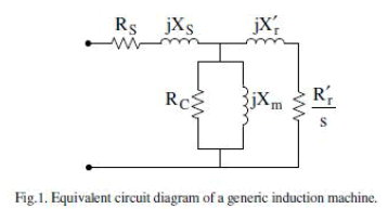
| Since the electrical resonance frequency is less than system nominal frequency, the slip is negative. Hence, the resistance Of the rotor (at the sub synchronous frequency from the armature terminals perspective) is negative likewise. Referring to the generic equivalent circuit of an SEIG depicted in Fig. 1, a self excitation circumstance appear when the magnitude of this resistance exceeds the sum of the armature and network resistance at a resonant frequency. |
| B) TI: The generator rotor torsional oscillation with the frequency m f induces armature voltage components at the frequencies given by |
 |
| When the sub synchronous frequency component e( ind ) f comes in close vicinity or matches with any of the electric resonance frequency, i.e., e f , the torsional oscillation and electrical resonance will be mutually excited resulting in SSR. |
| 2) Transient torques or transient SSR: Transient torques are those that originate from the system disturbances. System disturbances and faults cause sudden changes in the network, resulting in abrupt changes in the currents that will tend to oscillate at the natural frequencies of the network. The transient SSR usually occurs when the complement of the electrical network resonant frequency coincides with one of the torsional natural frequencies. |
INTRODUCTION TO SEN TRANSFORMER |
| and reactive power flows in the transmission line are affected simultaneously. |
| Consider that the point of compensation in the transmission line is at its sending end. Assuming that there are no changes in the transmission line’s impedance and the voltage at the receiving end, a power flow controller (PFC) can control the active and reactive power flows (Pr and Qr) to be a particular pair of values by modifying the sending-end voltage to a specific magnitude and phase angle. This can be accomplished by connecting a compensating voltage in series with the line using a shunt–series power converter. The shunt–series-type converters have been installed in several locations to be used as unified power flow controllers (UPFCs). A ±160 MVA-rated UPFC demonstrated for the first time that the active and reactive power flows in a transmission line could be regulated independently while maintaining a fixed line voltage at the point of compensation. |
 |
| Electric power flow through an AC transmission line is a function of the line impedance, the magnitudes of the sending-end voltage (Vs) and the receiving-end voltage (Vr), and the phase angle (V) between these voltages. Figure 9- 1 shows a simple transmission line represented with only a reactance (X) and the related expressions for active and reactive power flows at the receiving end of the line. |
| Power flow control parameters (voltage magnitude, its phase angle, and line reactance) can be regulated with the use of the following, now considered conventional, equipment: |
| 1. Voltage regulating transformer (VRT), shunt or parallel-connected switched inductor/ capacitor, static var compensator (SVC), or static synchronous compensator (STATCOM) for voltage regulation |
| 2. Phase angle regulator (PAR) or phase shifting transformer (PST) for phase angle regulation |
| 3. Thyristor-controlled series capacitor (TCSC) for series reactance regulation. |
| By regulating any one of the power flow control parameters using one of the above conventional solutions, both the active |
WORKING OF SEN TRANSFORMER |
A. Voltage Regulator |
| The VRT is an autotransformer, shown in Figure , that provides three-phase, bipolar compensating voltages (Vs_sA, Vs_sB, and Vs_sC). The uncompensated transmission line’s three-phase sending-end voltages (VsA, VsB, and VsC) are regulated at Vs_A, Vs_B, and Vs_C when the compensating voltage is connected in series with the line at the point of compensation. Since the compensating voltage is a fraction of the line voltage, the rating of the autotransformer is only a fraction of the transmitted power. As shown in Figure the VRT operates as an autotransformer. The exciter unit consists of a three-phase (A, B, and C), Y-connected primary windings that are connected in shunt with the line. The three-phase primary windings are excited from the three-phase line voltages (VsA, VsB, and VsC). A three-phase, bipolar compensating voltages (Vs_sA, Vs_sB, and Vs_sC) that are either in phase or out of phase with the corresponding phase-to-neutral voltage are generated from the induced secondary voltages. |
B. Phase Angle Regulator |
| A PAR connects a voltage in series with the transmission line and in quadrature with the phase-to-neutral voltage of the transmission line as shown in Fig.3 The series-connected compensating voltage introduces a phase shift whose magnitude (for small change) in radians varies with the magnitude of the compensating voltage in per units where the phase-to-neutral voltage of the transmission line is the base voltage. In a typical configuration, a PAR consists of two transformers as shown in Fig.3 The first transformer (exciter unit) is called a regulating transformer and is connected in shunt with the line. Its primary windings are excited from the line voltage ( ), and a three-phase bipolar voltage is induced in the secondary windings. With the use of taps, a compensating voltage ( ) with variable magnitude and in quadrature with the line voltage is generated from the phaseto- phase voltage of the induced voltage of the regulating transformer. For series connection of this voltage, an electrical isolation is necessary. The second transformer (series unit) is called a series transformer and is excited from the phaseto- phase voltage of the regulating transformer. |
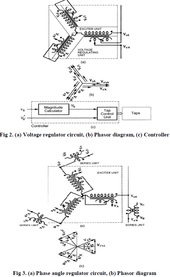 |
| The induced voltage of the series transformer is connected in series with the line.If the series transformer is a stepdown transformer, the primary windings of the series transformer as well as the secondary windings of the regulating transformer are high-voltage-rated and low-current-rated so that the taps on the secondary side of the regulating transformer can operate at a low current and can ride through a high fault current. Please note that a PAR can be realized with a singlecore transformer as well. In this case, the taps are always subject to carry high line current as well as even higher fault current. |
MODELLING OF SEN TRANSFORMER |
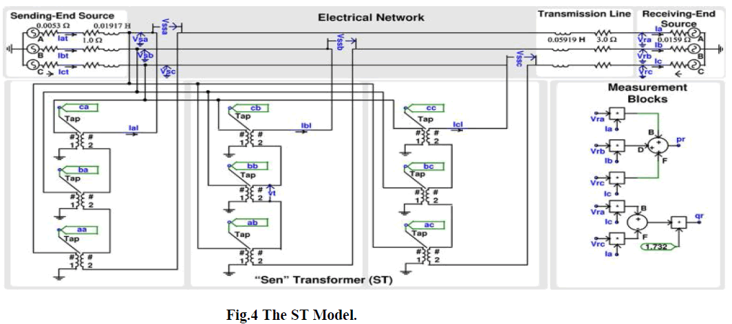
| A digital computer simulation model of the ST has been developed using matlab. The model consists of two subsystems: the electrical subsystem and the tap-selection algorithm subsystem. |
A. Electrical System |
| The electrical system is comprised of two ac systems connected by a three phase transmission line. The ST is connected at the sending end of the transmission line. Table I gives the parameters for both the ST and the network. |
| 1) Electrical Network Model: The ac sources at both sending and receiving ends are modeled as infinite sources with the same magnitude but at a phase difference of 20 (the receiving end voltage lags the sending end voltage). The transmission line is modeled as lumped series impedance. |
| 2) ST Model: The ST is a specially designed transformer with multiple windings having multiple tap positions in the secondary. The model for such a transformer is not available in matlab. Therefore, nine single-phase transformers, each having on-load tap changing capability have been used to model the ST. By using single-phase transformers, interphase. Mutual flux linkage and thus mutual inductance has not been considered, which may cause some discrepancies in the results. These nine single-phase transformers are modeled with a small resistance and leakage reactance as shown in Table I. Output voltages of three transformers (contributing from phase , and ) are added in series and then fed to one phase of the transmission line. The nine outputs (aa, ab, ac, ba, bb, bc, ca, cb, and cc) from the tap-selection algorithm supply the value of tap setting to all nine transformer Tap terminals. Should these outputs undergo any changes, the transformers readjust their tap positions and produce the required compensating voltages. |
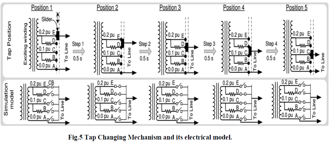
| b)Tap Changer Model: In a practical transformer, tap changing is performed through a tap selector, where a resistor or inductor is used in parallel with the tap positions to limit the current through a shorting winding segment between two consecutive taps. In Fig. 2, an example of tap-changing operation has been shown along with the equivalent matlab model for each position of the tap selector. Although, practical transformers with on load tap changers (OLTC), such as the ones from Reinhausen [8] use taps with voltage difference in the range of 0.02 p.u. to 0.067 p.u., in this model a voltage difference of 0.1 p.u. between taps has been assumed for theclarity of simulation. The time required to move the tap selector between adjacent tap positions is 2 s [8]. In order to move the tap selector from its initial position, terminal E (0.2 p.u.) to its final position, terminal C (0.1 p.u.), the following four steps of approximately 0.5 s each are performed. |
 |
 |
SIMULATION AND RESULTS |
| Step 1: In position 1, the tap selector is connected to ter- minal E; therefore, in the model the circuit breaker (CB) connecting terminal E to line is closed and the rest of the CBs are open. Now, the selector is moved to a position where it connects both terminal D and E; however, the current flows through terminal E alone. To model this situation, the CB connecting terminal D is closed. |
| Step 2: The tap selector moves further down and is connected to terminal D. The line current now flows through the resistor, and depending on the value of the resistance, a slight dip in the voltage may occur. In the model, CB connecting terminal E is opened. |
| Step 3: In this step, the tap selector is moved to a position, where it connects both terminals C and D. This is the situation where a circulating current will flow within the loop formed by the terminals C, D and the resistor. The higher the value of the resistor, the lower will be the circulating current, however, too high a value of resistance would cause a voltage sag. In the model, the CB connecting terminal C is now closed. |
| Step 4: In the final step, the tap selector is moved to allow contact with terminal C alone, which is the required final position. In the model, the CB connecting terminal D is opened. |
POWER SYSTEM CONFIGURATION |
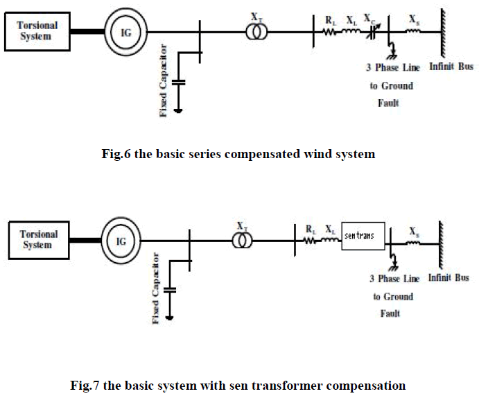
| The system investigated in this paper, depicted in Fig. 2, is the modified model of the well-known IEEE first SSR benchmark. Here, the wind farm is represented by a number of coherent IGs each of 1000 HP (0.746 MW) rating which is connected to the grid through a fixed series compensated line. In this study, based on the existing installed practical systems, the wind farm power output varies from 100 to 500 MW. The mechanical system of the wind turbine consists of a two-mass torsional system where one represents the wind turbine system and the other is for the set of IGs. The rated voltage and frequency are 539 kV and 60Hz, respectively. The transmission line is modeled with a reactance, a resistance, and a series fixed capacitive compensation reactance. Also a fixed shunt capacitor of 2000 μF per phase is utilized at the IG terminal to fulfill the reactive power support of the generator |
 |
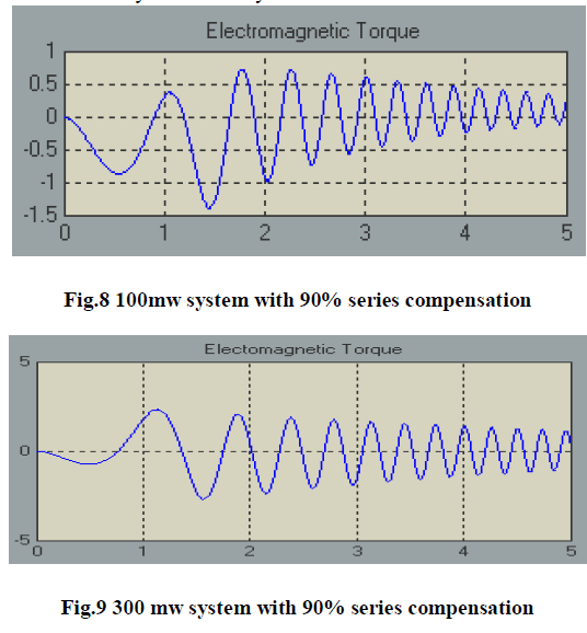
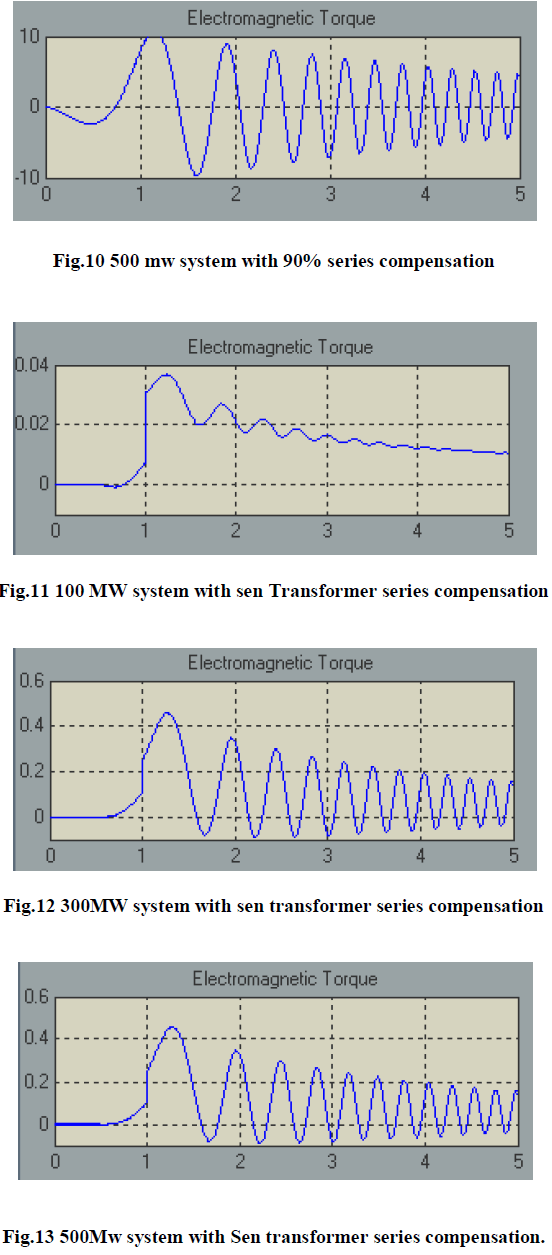
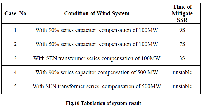
| The electromagnetic torque is obtained for WTG power outputs of 100, 300, and 500 MW to examine the onset of IG self-excitation. The results are depicted in Fig. 4. It is observed that for a power transfer “P” of 100 MW, the IG selfexcitation effect is not so prominent even with a series compensation level 90%. Oscillations are visible in the electromagnetic torque but they decay with time. However, as the power transfer level is increased to 300 MW, oscillations of high magnitude appear in the electromagnetic torque. When the power transfer level reaches 500 MW, the oscillations start growing and eventually make the system uncertain. |
 |
 |
 |
B. Effect of Sen Transformer |
| When a Sen Transformer is modeled and added to the wind system, the oscillation in electromagnetic torque is getting reduced. The SSR produced is less compared to n the simple capacitor bank series compensation. |
CONCLUSION |
| The modeling of 500MW wind system has been done using mat lab package .The SSR behavior of the system with simple capacitor compensation has been observed through the study of the behavior of oscillation in electromagnetic torque. As part of the analysis to reduce the SSR of the system SEN transformer was added, modeled and tested to show the effect on the electromagnetic torque oscillation for different power delivery. In conclusion significant reduction in SSR is shown by the stimulation of IEEE first bunch mark model. |
References |
|