ISSN ONLINE(2278-8875) PRINT (2320-3765)
ISSN ONLINE(2278-8875) PRINT (2320-3765)
Rohita P. Patil1, Prajakta P. Bharadkar2
|
| Related article at Pubmed, Scholar Google |
Visit for more related articles at International Journal of Advanced Research in Electrical, Electronics and Instrumentation Engineering
The LMS Adaptive filter has wide range of applications but it cannot support pipelined operations because of its recursive behaviour. An efficient architecture of Delayed LMS algorithm thus has been proposed that supports pipelining. The paper discuses about the DLMS algorithm and different architectures of DLMS adaptive filter in brief. These architectures concentrates on increasing usable frequency, minimize the adaption delay and area. The comparison between these various architectures based on critical path, hardware elements required is discussed.
Keywords |
| Adaptive Filter, LMS algorithm, DLMS Algorithm, Critical Path, Pipelining. |
INTRODUCTION |
| The adaptive filter itself can adjust its transfer function according to an optimizing algorithm and object can be achieved by the modification of its characteristics. They provide flexibility and accuracy in the field of communication and control. The LMS (Least Mean Square) algorithm is widely used because of its easy calculations and better convergence performance. LMS adaptive filter has wide range of applications in communication and DSP (Digital Signal Processing) such as predictor, system identification, noise cancellation, equalization. However the direct implementation of LMS algorithm has long critical path which is due to the complex inner product computations to obtain the filter output[1]. In order to avoid this long critical path, pipelining has to be introduced when it exceeds the desired sample period. The conventional LMS algorithm does not support pipelining. As a result, the high speed adaptive filters have been mainly based on adaptive lattice filter, which supports pipelining. Long [8] has showed that some delay can be added in the weights of LMS algorithm which modified LMS algorithm to DLMS algorithm supporting pipelined operations. As the LMS algorithm is well suited for software simulation but not for hardware implementations, DLMS(Delayed Least Mean Square) algorithm is introduced in order to provide VLSI(Very Large Scale Integration) implementations[7]. Fig. 1 shows the basic block diagram of adaptive filtering. |
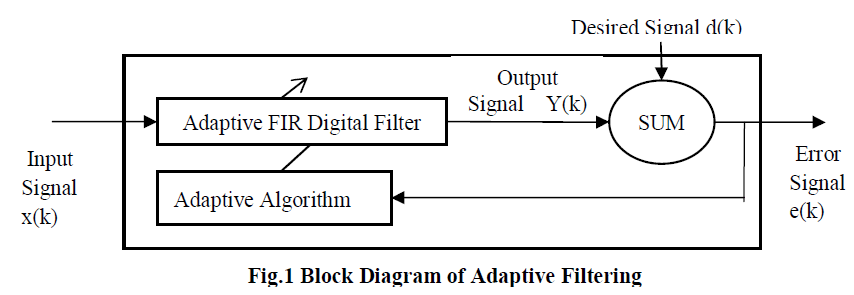 |
| The error signal e(k) can be generated by the output of the adaptive filter y(k) subtracted from a reference signal d(k). |
| When the e(k) has achieved its minimum value through the iterations of the adapting algorithm, the process is finished and its coefficients have converged to a solution. The final output from the adaptive filter matches closely the desired signal d(k). When the input data characteristics are changed, sometimes called the filter environment, the filter adapts to the new environment by generating a new set of coefficients for the new data. |
| The next section, we review the DLMS algorithm and in section III we will see the Related Work where the brief discussion on different DLMS adaptive filter architectures is given. Section IV discuses the comparison of these architectures on the basis of critical path, number of multipliers and adders required and the delay. Conclusion is given in section V. |
DLMS ALGORITHM |
| The general form of LMS algorithm is given by following equation[8] |
 |
| In the pipelined designs with m pipeline stages, the error en becomes available after m cycles. Here m is called the “adaptation delay.” Hence the DLMS algorithm uses the delayed error en−m. en-m is the error corresponding to (n − m)th iteration for updating the current weight instead of the recent-most error. The weight-update equation of DLMS adaptive filter is given by |
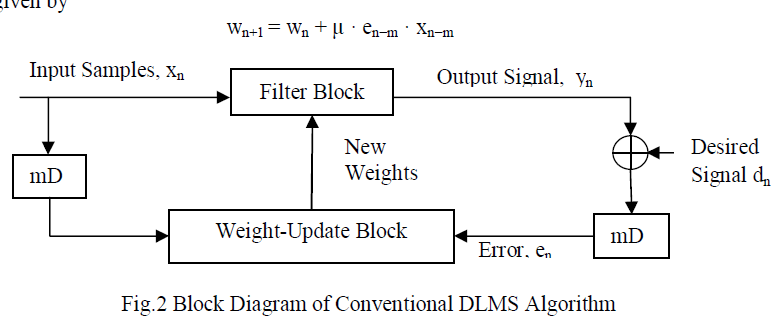 |
| The block diagram of the conventional DLMS adaptive filter is shown in Fig.2. Here the total adaptation delay of m cycles equals to the delay introduced by the filtering process and the weight-update process. |
RELATED WORK |
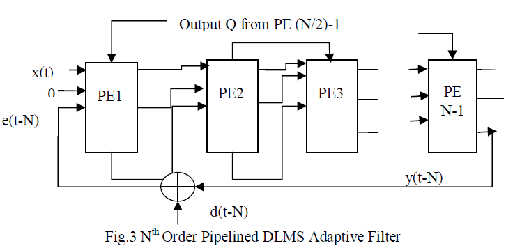
| 1) Various systolic architectures have been implemented using the DLMS algorithm. They are mainly concerned with the increase the maximum usable frequency[7]. Problem with these architectures was they were involving a large adaptation delay. This delay is of ~ N cycles for filter length N, which is quite high for large order filters. Fig. 3 shows Nth order pipelined DLMS adaptive filter implemented by Mayer and Agrawal. |
 |
| 2) Large adaption delay reduces the convergence performance of the adaptive filter. Thus to reduce the adaptation delay, Visvanathan et al. [6] have proposed a modified systolic architecture. This architecture has minimal adaption delay and input/output latency. Fig. 4 shows folded systolic array for DLMS algorithm with Boundary Processor Module (BPM) and Folded Processor Module (FPM). The complex FPM circuitry of previous designs has been replaced by simple 2:1 mux along with registers. Appropriate numbers of registers are moved from BPM to FPM. Processors are pipelined. |
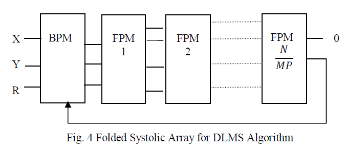 |
| The key transformations used are slow down and folding to reduce adaption delay. With the use of carry-save arithmetic, the systolic folded architecture can support very high sampling rates but are limited by the delay of a full adder. |
| 3) Tree methods enhance the performance of adaptive filter but they lack in modularity, local connection. Also with the increase in tree stages critical period also increases. In order to achieve a lower adaption delay again, Van and Feng [10] have proposed a systolic architecture, where they have used relatively large processing elements (PEs). The PE combines the systolic architecture and tree structure to reduce adaption delay. But it involves the critical path of one MAC operation.[5] |
| 4) Ting et al. [4] have proposed a fine-grained pipelined design. Pipelining is applied to multipliers to reduce the critical path. Rich register architecture of FPGA can allow pipelining at CLB level, i.e., fine grained pipelining. Thus Virtex FPGA technology is used. Each CLB acts as a 1 bit adder. Various sized ripple carry adders are allowed by dedicated arry logic. This design limits the critical path to the maximum of one addition time and hence supports high sampling frequency. But as large numbers of pipeline latches are being used it involves a lot of area overhead for pipelining and higher power consumption. Also the routing of FPGA adds very large delay. |
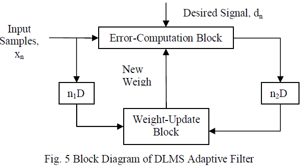
| 5) Meher and Maheshwari modified the conventional DLMS algorithm to an efficient architecture with inner product computation unit and pipelined weight update unit[3]. Adaption delay of DLMS adaptive filter can be divided into two parts: one part is delay introduced in pipelining stages of filtering and second part is delay introduced in pipelining stages of weight updation. Based on these parts DLMS adaptive filter can be implemented as shown in Fig.2 |
 |
| The weight-update equation of the DLMS algorithm is given by |
 |
| Computations of the error-computation block and the weight-updation block are decoupled by the modified DLMS algorithm. This allows optimal pipelining by feedforward cut-set retiming of both these sections separately to minimize the number of pipeline stages and adaptation delay. |
| 6) Further Meher and Maheshwari [2] have proposed a 2-bit multiplication cell along with an efficient adder tree for pipelined inner product computation. This architecture minimizes the critical path and silicon area without increasing the number of adaptation delays. Both error computation and weight update block is implemented using 2-bit multiplication cell. |
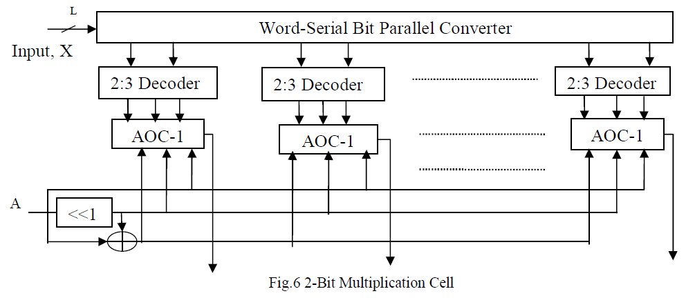 |
| The L/2 number of AND/OR cell (AOC) and 2-to-3 decoders makes the complete multiplication cell which multiplies word A and input x each of l bits. Each AOC contains 3 AND cells and an OR-tree of 2 OR cells. Each AND gate takes (W + 2)-bit input D and a single bit input b. Each OR gate takes (W +2) input pair words. The 2-to-3 decoder takes a 2- bit input and produces three output b0, b1 and b2. The AOC perform a multiplication of input operand A with two-bit digit (Xl, xo), such that the 2-bit multiplication cell. |
COMPARISON OF DIFFERENT ARCHITECTURES |
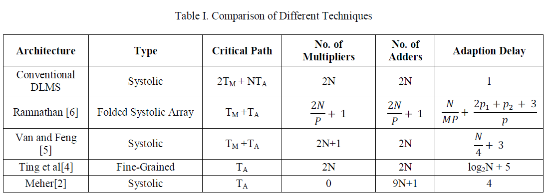
| According to the survey, comparison of the architectures is listed in table I based on critical path, multipliers required, adders required and the delay. TM refers to time required for the multiplication and the TA refers to time required for the addition. N is the filter length. In case of folded systolic array p is slow down factor and M is fanout lines. |
 |
CONCLUSION |
| In this paper, the different DLMS filter architectures have been discussed. Systolic architectures tried to improve the operating frequency of the adaptive filter. Further efforts have been taken to reduce the area required for the implementation of the adaptive filter using DLMS algorithm. Meher have been proposed an efficient architecture that requires lesser area along with less adaption delay. For this improvement he has used pipelined inner product computation scheme. |
References |
|